



Product Features:
1. Machine mainly application and Basic components
1.1 Mainly application
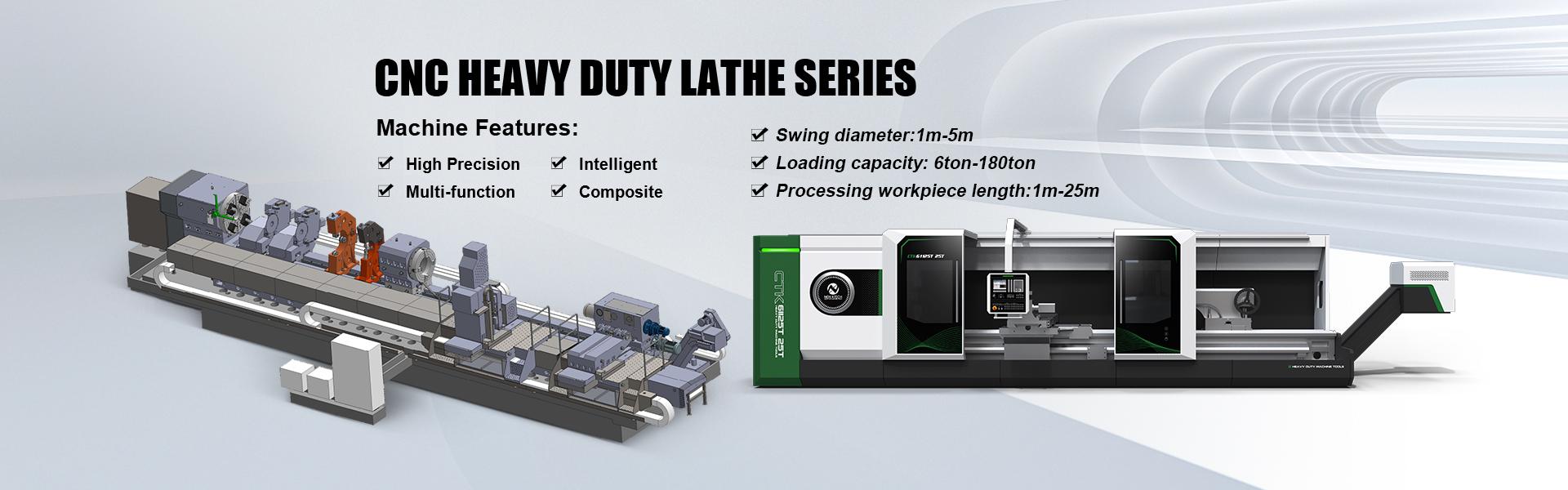
This machine is a CNC heavy-duty horizontal lathe, suitable for applications in the energy, chemical, light industry, electromechanical, papermaking, aerospace, and aviation industries.
The machine is capable of performing various turning operations on large shaft-type workpieces (or cylindrical parts), including contoured surfaces and facing.
The machine is equipped with a single tool post.
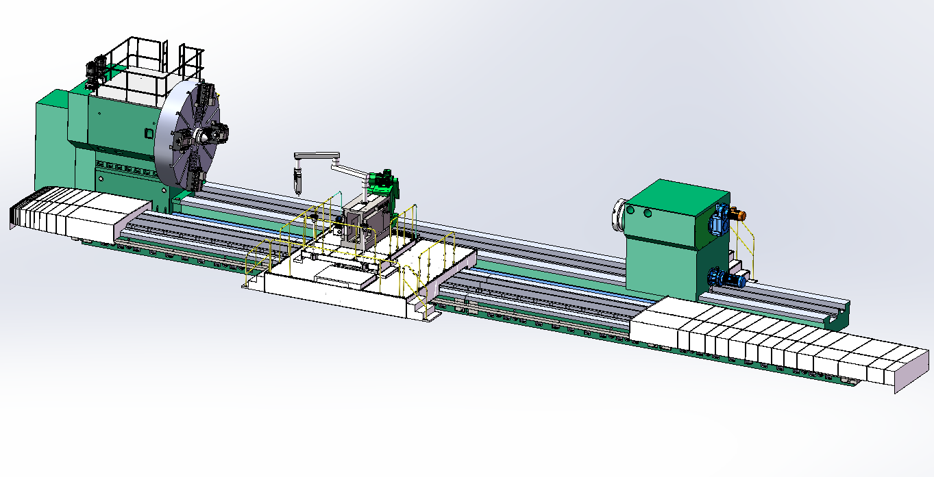
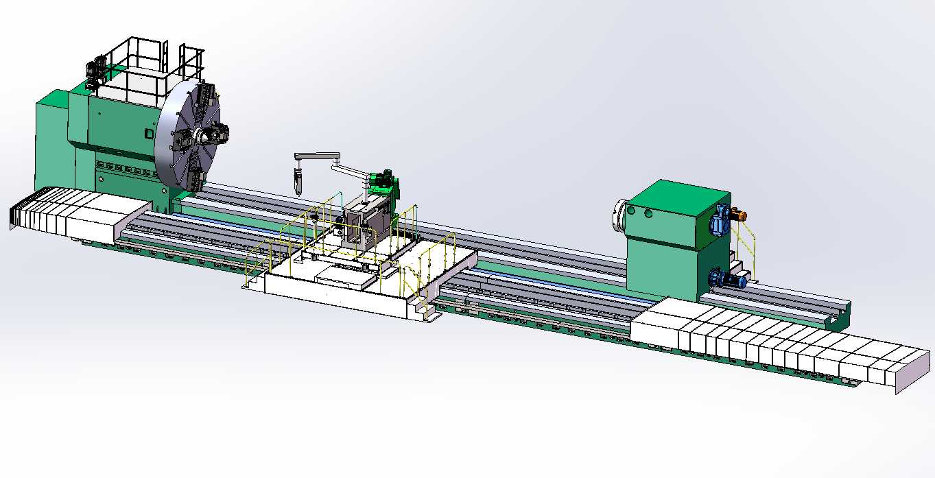
Product schematic diagram (reference)
1.2 Basic Components
The standard configuration includes: workpiece bed, tool post bed, headstock, tailstock, carriage, box-type tool post, motor base, hydrostatic steady rest, drag chain device, chip conveyor unit, hydraulic system, cooling system, and electrical control system.
The CNC system of the machine tool can be equipped with a Siemens 828D CNC system as per user requirements. The spindle drive system adopts a Siemens 6RA80 speed control system. The longitudinal (Z-axis) employs dual servo motors with dual pinions and a helical rack for backlash elimination, while the transverse (X-axis) uses a ball screw drive. The longitudinal and transverse movements of the tool post are driven by AC servo motors, and both the X and Z axes utilize precision linear encoders as position feedback elements, forming a closed-loop position control system.
2. Technical Parameters
2.1 Main Parameters
2.1.1 Max. swing diameter over bed ………………………………………………φ2600mm
2.1.2 Max. swing diameter over carriage ………………………………………φ2200mm
2.1.3 Max. workpiece length ……………………………………………………14000mm
2.1.4 Max. workpiece weight between centers …………………………………150t
2.1.5 Distance from spindle center to bed ……………………………………1500mm
2.1.6 Faceplate max. torque ………………………………………………150 kN·m
2.1.7 Tool post cutting force …………………………………………………150 kN
2.1.8 Center taper angle ………………………………………………………75°
2.2 Main Drive Parameters
2.2.1 Spindle speed steps (mechanical 2-range) ……………………………Stepless
2.2.2 Spindle speed range ……………………………………………0.5–100 r/min
2.2.3 Faceplate diameter …………………………………………………φ2500mm
2.2.4 Spindle taper dimension ………………………………φ285.775mm; 1:4
2.2.5 Front bearing diameter of spindle ……………………………………φ800mm
2.3 Feed Drive Parameters
2.3.1 Feed steps ……………………………………………………………Stepless
2.3.2 Longitudinal feed range of carriage ……………………0.1–1000 mm/min
2.3.3 Cross feed range of carriage ……………………………0.1–100 mm/min
2.3.4 Rapid traverse speed (longitudinal) …………………………4000 mm/min
2.3.5 Rapid traverse speed (cross) ………………………………1500 mm/min
2.3.6 Max. cross travel …………………………1400 (tool slide travel: 450mm)
2.3.7 Max. longitudinal travel ……………………………………………14000mm
2.3.8 Tool holder section size …………………………………………70×80mm
2.4 Tailstock Parameters
2.4.1 Tailstock quill travel ………………………………………………250mm
2.4.2 Tailstock quill feed speed ………………………………………50 mm/min
2.4.3 Tailstock traverse speed ………………………………………2000 mm/min
2.4.4 Tailstock taper dimension ……………………………φ285.775mm; 1:4
2.4.5 Tailstock quill diameter …………………………………………φ800mm
2.5 Motors
2.5.1 Main motor (Z4 DC variable-speed motor power) …………………143 kW
2.5.2 Feed AC servo motor: X-axis …………………………………………1FT7 70 N·m ×2
2.5.3 Tailstock traverse motor power ………………………………………15 kW
Speed ……………………………………………1500 r/min
2.5.4 Tailstock quill motor power …………………………………………11 kW
- Speed ……………………………………………1500 r/min
2.6 Main Drive System ……………………………………………SIEMENS 6RA80
2.7 Hydrostatic Steady Rest Supporting Diameter Range ……φ250–φ800mm
(Each of two rests supports max. 80t)
3. Machine Tool Accuracy
Unspecified parameters must comply with the Chinese national standard GB/T 23569-2009, "Test Conditions for Heavy-Duty Lathes—Testing of Accuracy."
- Runout of Spindle Center (Axial): <0.01 mm
- Runout of Spindle Center (Radial): <0.01 mm
- Runout of Tailstock Center (Axial): <0.01 mm
- Runout of Tailstock Center (Radial): <0.01 mm
- Workpiece Surface Roughness (Turning, Cylindrical Surface): Ra 1.6
- Radial Runout of Finish-Turned Test Piece: <0.01 mm
- Face Runout of Finish-Turned Test Piece: <0.01 mm
- Roundness of Machined Workpiece: 0.01 mm
- Cylindricity of Machined Workpiece: 0.015/1000 mm
Positioning Accuracy of Axes:
- X-axis: ≤ 0.015 mm
- Z-axis: ≤ 0.01/1000 mm
- Z-axis (long travel): ≤ 0.08/14000 mm
Repeated Positioning Accuracy:
- X-axis: ≤ 0.01/1400 mm
- Z-axis: ≤ 0.07/14000 mm
4. Main structure of machine tool
4.1 Bed
This machine tool features a separate four-guideway layout with rectangular guideways. The total width of the bed guideways is increased, with two serving as the carriage guideways (width: 1700 mm), employing constant-flow hydrostatic guideways, and the carriage bed is fully enclosed.The other two guideways are for the workpiece (width: 1500 mm). The workpiece bed is partially enclosed in segments according to the workpiece length, ensuring optimal force distribution, stable cutting performance, and favorable carriage loading conditions, making it suitable for heavy-duty cutting.
Due to the separated bed structure, the deformation of the workpiece bed caused by workpiece gravity does not affect the tool post bed, maintaining original accuracy and ensuring machining quality.
The separated four-guideway bed design isolates the main drive system from the feed drive system, preventing mutual vibration interference, which enhances machining quality and improves the machine tool’s vibration resistance.
The four-guideway separated bed layout significantly reduces mutual thermal deformation effects, contributing to machining accuracy.
The bed is supported on foundation leveling blocks and fixed with anchor bolts after adjustment. The workpiece bed and tool post bed are separately connected to the foundation, forming an integrated structure with good contact precision, ensuring guideway accuracy. Each bed can be adjusted independently for easier precision maintenance. Since anchor bolts and leveling blocks are installed every 500 mm along the bed, the connection stiffness between the bed and foundation is enhanced, resulting in higher overall rigidity, improved machining accuracy, and extended service life.
A large space exists between the workpiece bed and tool post bed, facilitating the installation of a chain-type chip conveyor to discharge chips into a collection tank
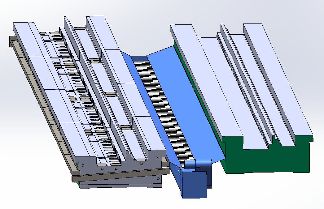
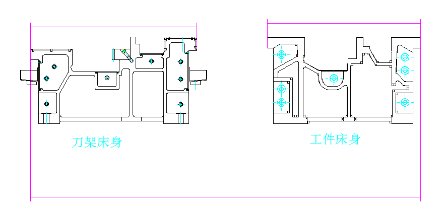
Bed diagram
4.2 Headstock
The headstock body features a large-diameter through-shaft structure, driven by a Z4 series DC variable-speed motor. The spindle system adopts a Siemens fully digital 6RA80 DC drive unit. Through combined field-weakening and voltage regulation speed control, as well as a hydraulically operated two-speed mechanical gearbox, the spindle achieves the specified speed range. The main motor is connected to the main transmission mechanism via an elastic coupling. Power is transmitted through mechanical gear shifting and helical gear pairs to the faceplate, ensuring the required torque output. All high-precision gears in the main transmission mechanism undergo hardening, grinding, and necessary profile modification.
The spindle bearings use adjustable double-row radial short cylindrical roller bearings with controllable radial clearance. The spindle journal and locating taper hole are hardened and ground. The spindle center adopts a flanged short-taper shank design, secured to the spindle nose with screws and an interference-fit taper for high rigidity and durability.
A flow monitor is installed in the recess on the rear wall of the headstock to trigger an alarm if lubrication flow is insufficient. An encoder is mounted at the rear end of the spindle to enable feed-per-revolution, thread cutting, and constant surface speed machining functions.
The headstock is equipped with an independent hydraulic control system and lubrication system.
The headstock is mounted on the headstock base, which is in turn fixed to the machine bed.
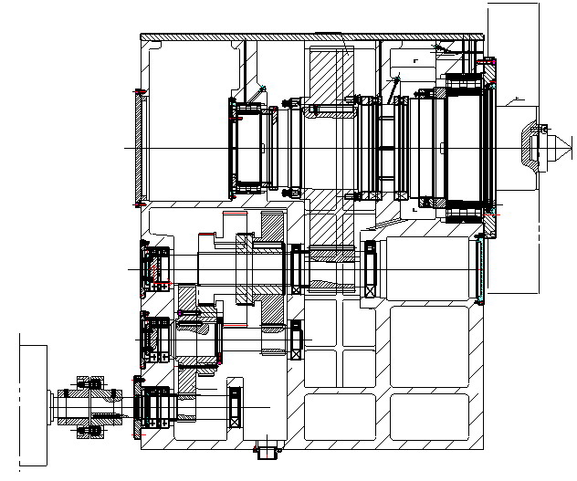
Schematic diagram of headstock transmission
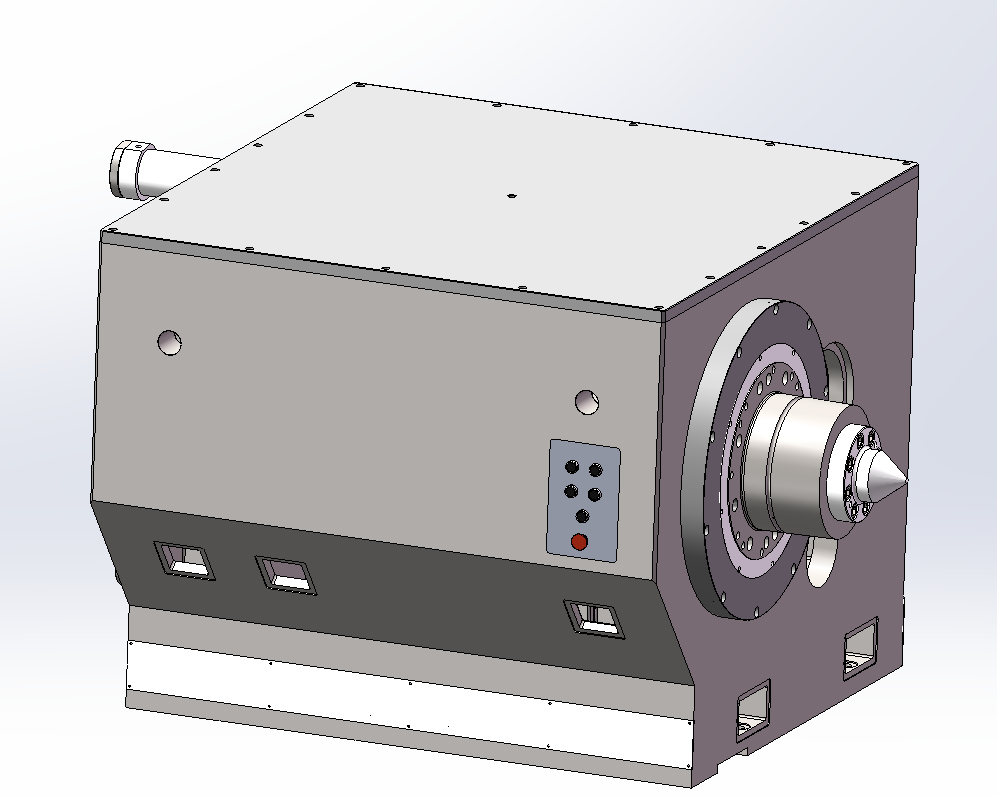
Schematic diagram of Headstock
The headstock is equipped with an oil temperature-controlled tank that automatically regulates oil temperature to reduce thermal deformation of the headstock. A flow relay is installed upstream of the oil distributor for low-oil alarm, ensuring adequate lubrication for the spindle assembly and main drive mechanism. Temperature sensors are mounted at the spindle bearing locations inside the headstock to monitor bearing temperature rise. When excessive temperature rise occurs, the alarm system triggers a warning to alert the operator.
4.3 Faceplate
The clamping of the workpiece is accomplished by four mechanical force-amplifying jaws at the front end of the chuck. The screw drive enables the jaws to rapidly approach the clamping position, and the workpiece is secured using the force-amplifying screw inside the jaw holder.
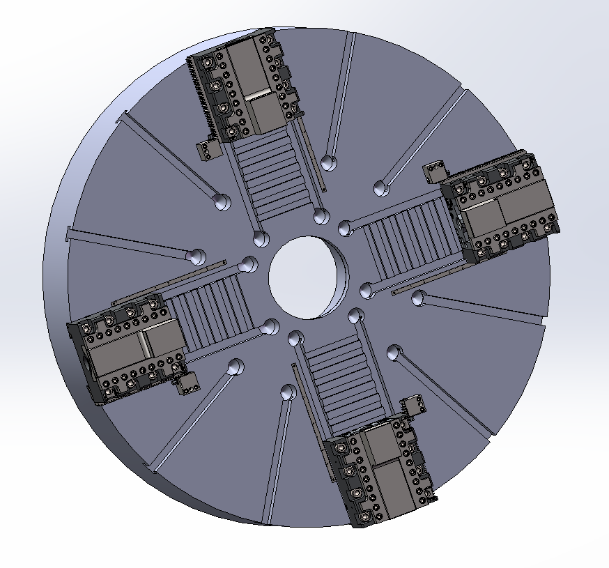
Schematic diagram of chuck
4.4 Tailstock
The tailstock consists of an upper body and a lower body. The housing is made of high-quality low-stress cast iron. The upper body is equipped with a tailstock spindle, sleeve, force-measuring device, and sleeve movement mechanism, while the lower body contains the tailstock's overall movement mechanism.
The lower body is driven by an electric motor with a travel speed of 2000 mm/min. The motion is transmitted via a motor-reducer pair, a set of reduction gears, and a worm-and-rack mechanism, allowing it to move along the workpiece bed. Once positioned, it is clamped to the bed by two rows of disc springs, employing a mechanical clamping and hydraulic release system. The worm-and-rack mechanism features a self-locking function to prevent backward movement.
The upper body of the tailstock houses a hydraulic force-measuring device for the spindle. The front end of the tailstock sleeve spindle is supported by a double-row radial roller bearing, providing high rigidity similar to the main spindle structure. The center is identical to that of the headstock, featuring a flange-type short-taper shank center. It is secured to the front end of the spindle via screws and an interference-fit tapered surface. The flange end face tightly presses against the spindle's front face, ensuring high rigidity in the center system.
Both the front and rear sides of the tailstock are equipped with an electric contact pressure gauge. The preset pressure can be selected according to the workpiece weight based on the force indication plate. When the sleeve advances to clamp the workpiece, the sleeve movement motor automatically stops once the preset clamping force is reached.
A hydraulic system is integrated into the tailstock body to supply pressure oil for clamping or releasing.
Lubrication is provided by an intermittent, timed, and quantitative automatic lubrication station.
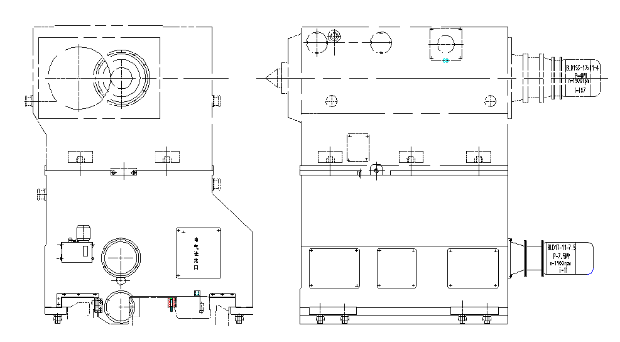
Tailstock schematic diagram
4.5 Saddle
The saddle consists of a longitudinal slide (Z-axis) and a cross slide (X-axis). The guideways for both longitudinal and transverse movements are two closed hydrostatic guideways each. The full hydrostatic system generates an oil film on the guideways, with appropriate oil pressure maintained between the oil pockets and the tool post to ensure flotation. The hydrostatic guideways are supplied by a dedicated oil tank equipped with an automatic oil temperature control system.
The saddle is driven by an AC servo motor, which transmits motion through a ratio gear and a bidirectional backlash elimination mechanism to a dual small helical gear-and-rack system. This drives the entire longitudinal slide along the Z-axis. The backlash between the dual small helical gears and the rack is eliminated by a disc spring cylinder pushing the central shaft. When there are minor variations in the rack pitch, the axial movement of the central shaft automatically compensates, ensuring zero-backlash meshing between the small helical gears and the rack. This guarantees high precision and stability throughout the tool post's movement. The longitudinal axis employs a high-precision, hardened Grade 6 rack.
The cross slide is driven by a single AC servo motor via a ball screw, enabling forward and backward movement along the transverse direction. It is equipped with a Heidenhain grating scale, forming a full closed-loop control system.
Both the longitudinal and transverse guideways of the tool post are fitted with telescopic way covers for protection.
4.6 Box-type Tool Post
The box-type tool post is suitable for rough and finish machining of various shaft-type workpieces, particularly for heavy-duty cutting (rough machining) as well as machining step shafts, deep grooves, and end faces.
This tool post mainly consists of a tool post body, large tool plates, and a tool plate movement mechanism. The tool plates are arranged on both sides of the tool post body and can extend and retract independently, secured to the tool post body via clamping plates.
The tool plate movement is electrically driven, automatically clamping in place once the desired position is reached.
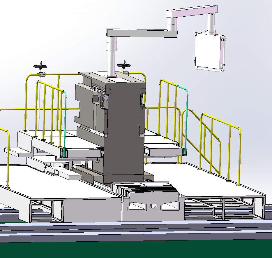
Appearance diagram of Box type Tool Post
4.7 Chip Conveyor
The machine tool is equipped with a chip conveyor installed between the two beds to transport chips and discharge them into a chip collection bin (the chip bin shall be prepared by the user).
4.8 Hydrostatic Steady Rests
The machine tool is equipped with two sets of hydrostatic steady rests. Each steady rest adopts three sliding columns, with a slider mounted on the upper end of each column. The steady rest moves along the bed via a motor-gear-rack transmission system. The hydrostatic steady rest allows the tool post to pass through.
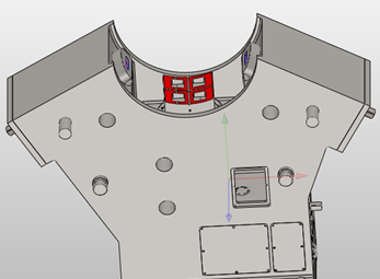
Appearance schematic diagram of hydrostatic steady rest
4.9 Machine Hydraulic System
The hydraulic system of this machine consists of the following components:Headstock hydraulic system;Tool post and carriage hydraulic system (including the hydrostatic system);Tailstock hydraulic system
4.9.1 Headstock Hydraulic System
This hydraulic system primarily controls spindle speed changes in the headstock while also providing lubrication for bearings, gears, and other transmission components inside the headstock. The hydraulic power unit is mounted on one side of the headstock, with oil pipes routed from the power unit through trenches to the headstock. After lubrication, the oil freely flows back to the power unit’s oil tank via return pipes. To maintain the oil temperature within a stable range, an oil cooler is installed on the power unit to prevent adverse effects on machine performance due to excessive oil temperature.
4.9.2 Tool Post and Carriage Hydraulic System (Including Hydrostatic System)
The tool post and carriage hydraulic system mainly controls the following functions:Hydrostatic guideways for the longitudinal carriage (saddle) and cross slide;Clamping and releasing of the tool holder;Backlash elimination in the apron mechanism;
The hydraulic power unit is installed in a pit on one side of the tool post bed and serves as the power source for the tool post hydraulic system, as well as the supply and return station for the hydrostatic system. To ensure stable oil temperature, an oil cooler is installed beside the power unit, preventing machine performance degradation due to excessive oil temperature.
Hydraulic and hydrostatic oil pipes run through trenches and pass through the tool post cable carrier, connecting to the hydraulic control valve block and hydrostatic system mounted on the carriage.
Longitudinal Carriage and Cross Slide Hydrostatic System
The hydrostatic system for the tool post carriage consists of a control valve block and capillary restrictors. Hydrostatic oil is distributed through individual restrictors to the respective oil chambers of the longitudinal carriage and cross slide hydrostatic guideways, ensuring that both carriages remain in a hydrostatic floating state.
4.9.3 Tailstock Hydraulic System
The tailstock hydraulic system is installed within the tailstock body. It primarily controls the clamping and releasing of the tailstock body, the clamping and releasing of the tailstock sleeve, and the lubrication of the tailstock spindle. This system operates as a high-pressure system with a pressure of 21 MPa. Under normal conditions, the system remains in pressure relief mode. When the tailstock body and guideway or the sleeve require releasing, the control pressure increases, actuating the control valve to complete the operation. Both the tailstock body (to the bed) and the sleeve employ spring clamping and hydraulic releasing.
4.9.4 Hydrostatic Steady Rest Hydraulic System
The hydrostatic steady rest hydraulic system supplies hydraulic power to the hydrostatic steady rest, including: the hydrostatic bearing cavity of the intermediate support column, the intermediate hydraulic cylinder, and the oil lubrication for the two side support columns.
4.10 CNC and Electrical Control System of the Machine Tool
4.10.1 The machine tool is equipped with a SINUMERIK 828D CNC system from Siemens.
4.10.2 The spindle is driven by a DC motor, with a Siemens 6RA80 digital drive for speed regulation, and is equipped with a spindle encoder. The X and Z axes are driven by Siemens AC servo motors. The main operator panel features a color LCD display, providing display functions and full access to the core components of the SINUMERIK system. The machine is also equipped with a handheld unit (HHU).
**Machine features:**
- **Graphical programming software on the machine.**
- **Helical and cylindrical interpolation programs.**
- **Interfaces: Ethernet, USB, PCMCIA, and RS232.**
When using the following algorithms to process the part, the possibility of independent operation for each support: - Left support across the entire machining area; - Right support across the entire machining area; - Both supports operating simultaneously; - Both supports operating based on independent programs and in different modes. | |
The remote control panel installed on each operator platform shall include all necessary controls for machine operation. | |
Touchscreen control panel with LCD display | |
Each support shall have a manual control panel.The manual control panel must provide control for all motion axes as well as panel functions | |
Graphical programming software on the machine. | |
Helical and cylindrical interpolation programs | |
Interfaces: Ethernet, USB, PCMCIA, and RS232. |
4.11 Machine Tool Painting
The paint color of the machine tool shall be determined in consultation with the user before spraying.
5. List of main accessories
Serial number | Name | Specifications | Quantity | Purpose | place of origin |
1 | Spindle bearing | 1 set | Headstock Spindle | NSK | |
2 | Tailstock spindle bearing | 1 set | Tailstock spindle | NSK | |
3 | Spindle Speed Regulation System | 6RA80 | 1 | Main motor drive | Domestic Premium Brand |
4 | Cross Ball Screw | 1 | TAIWAN DTK | ||
5 | CNC System | Siemens Sinumerik 828D | 1 | ||
6 | AC servo drive | Siemens | 1 set | Axis Drive | |
7 | Guideway Cover | 1 | Shandong Qingyun | ||
8 | Automatic Chip Conveyor | 1 | Chip removal | Yantai | |
9 | Cable Carrier | 1 | HANGZHOU JIAJI | ||
10 | Main motor | 4 | Spindle drive | SIMA | |
11 | Feed motor | 4 | Tool Post Movement | Siemens | |
12 | Push button station | 1 | DESITAI | ||
13 | Electrical Cabinet | 1 | WUXI or XIANGFAN | ||
14 | Rotary encoder | 1 | spindle | Siemens | |
15 | X Z-axis Linear Encoder | 1 | Position Feedback Device | FAGOR |
6. Supply list
6.1 Scope of supply of mainframe
Serial number | Supply Name | Units | Quantity | remark |
1 | Workpiece bed | set | 1 | |
2 | Tool Post Bed | set | 1 | |
3 | Headstock | set | 1 | |
4 | Tailstock | set | 1 | |
5 | Saddle | set | 1 | |
6 | Box-Type Tool Post | set | 1 | |
7 | Main Motor Mount | set | 1 | |
8 | Chip Conveyor | set | 1 | |
9 | Cable Carrier (Drag Chain) | set | 1 | |
10 | Foundation Mounting Kit | set | 1 | |
11 | Standard Tool Kit | set | 1 set | |
12 | Hydraulic control system | set | 1 | |
13 | Hydrostatic Steady Rests | set | 2 |
6.2 Randomization data
No. | Name | Units | Quantity | Offer time | remark |
1 | Packing list | copy | 1 | With Machine | |
2 | Machine Tool Operation Manual | set | 1 | With Machine | Mechanical, electrical |
3 | Certificate of conformity | Copy | 1 | With Machine | |
4 | System Diagnostic Instructions | set | 1 | With Machine | |
5 | System Programming Manual | set | 1 | With Machine | |
6 | "System Operation Guide" | set | 1 | With Machine | |
7 | Main Component Documentation | copy | 1 | With Machine |
7.Quality Control and Inspection
The machine tool is manufactured in accordance with relevant national standards, and the following technical documents for quality control and inspection have been established:
a. "Inspection Report for CK61315×80×63 CNC Heavy-Duty Horizontal Lathe";
b. "Criticality Classification List for Major Components of CK61315×80×63 CNC Heavy-Duty Horizontal Lathe";
The factory's Quality Management Center conducts inspections based on the above documents to ensure compliance.
After assembly, the machine undergoes a thorough inspection as specified in the 《Inspection Report for CK61315×80×63 CNC Heavy-Duty Horizontal Lathe》, including cutting tests. Upon successful completion, a 《Certificate of Conformity for CK61315×80×63 CNC Heavy-Duty Horizontal Lathe》 is issued and provided to the customer for record-keeping.
8.Major National and Industry Standards Applied to This Machine Tool
ZBJ50016-89 –《Metal-Cutting Machine Tools – General Hydraulic Systems》
GB15760-2004 –《General Safety Requirements for Metal-Cutting Machine Tools》
GB9061-1988 – 《General Technical Specifications for Metal-Cutting Machine Tools》
JB/T10051-1999 –《General Technical Specifications for Hydraulic Systems of Metal-Cutting Machine Tools》
GB 5226.1-2002 –《Electrical Equipment of Industrial Machines – Part 1: General Requirements》
GB/T23569-2009 –《Testing Conditions for Heavy-Duty Horizontal Lathes – Accuracy Testing》
9.Quality Assurance and After-Sales Service
Our company has been certified under ISO 9001:2000 Quality Management System and takes full responsibility for product quality, including compensation for losses caused by design, manufacturing, or service defects.
9.1 Design and Manufacturing Commitments:
a. All design and manufacturing processes comply with the signed technical agreement and relevant national/industry standards. Except for mating surfaces, all metal components undergo anti-corrosion treatments (chrome plating, zinc plating, bluing, or painting). We will repair any surface damage incurred during transportation or installation.
b. We guarantee that the equipment is technologically mature, reliable, and advanced.
c. We take full responsibility for the quality of purchased electromechanical components.
d. The customer may supervise the manufacturing process.
9.2 After-Sales Service Commitments:
a. Our technicians will provide training to operators and maintenance personnel to ensure proper operation and upkeep.
b. For quality issues, we will respond within 4 hours (via phone, fax, or email) or dispatch personnel within 48 hours, resolving faults within 3 working days. Our staff will remain on-site until the issue is resolved.
c. The warranty period is one year after final acceptance.
d. We ensure timely supply of spare parts with guaranteed compatibility and interchangeability.
e. During the warranty period, defective parts due to normal use will be replaced free of charge, with an additional one-year warranty for replaced components.
f. We provide lifetime technical support for operation, maintenance, repair, and upgrades.
10.Acceptance
Machine acceptance is conducted in two stages:
10.1 Pre-Acceptance:
The buyer shall arrive at the manufacturer’s facility within one week of receiving the completion notice. The seller will provide acceptance criteria and related documentation. Upon successful pre-acceptance, both parties will sign a Pre-Acceptance Report before disassembly and shipment.
10.2 Final Acceptance:
Conducted after on-site installation and commissioning. A Final Acceptance Report will be signed upon approval, marking the start of the warranty period. Key acceptance items include:
a. Geometric accuracy inspection;
b. Working accuracy inspection;
c. Functional testing;
d. Load capacity verification.
11.Installation & Commissioning
Upon arrival at the customer’s site and receipt of notification, our engineers will arrive within 5 days to perform installation, commissioning, and test runs. The process must be completed within 60 days, culminating in final acceptance. The buyer shall provide necessary support (e.g., personnel, lifting equipment, tools, and materials).
Product Parameters:

Whatsapp Code


 +86-151 6596 4868
 +86-151 6596 4868
 +86-151 6596 4868
 susan@novatechlathe.com
