


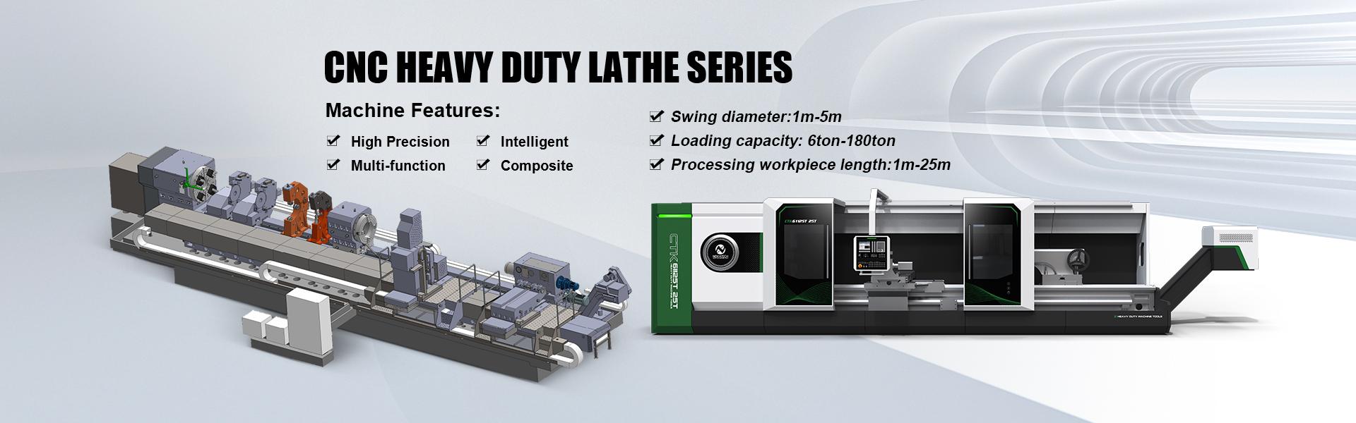

Product Features:
CK84100x10M/20T
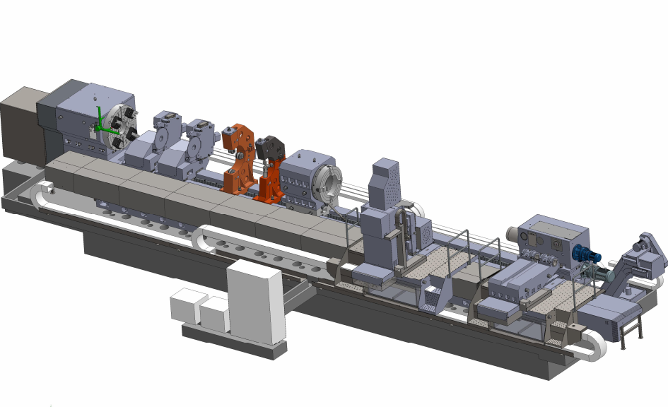
1. Machine Description
This machine is mainly used for processing the plain roller,piercer roller, also can turn the outer circle, end-face,groove, taper,thread and revolution surface of the rotary parts .
This machine is a roller lathe developed independently based on our company's years of experience in producing heavy-duty horizontal lathes and the characteristics of the processed workpiece. This machineadopts a screw drive in the horizontal direction (X-axis of the tool holder) and a precision rack and pinion drive in the longitudinal direction (Z-axis of the bed).
The entire machine adopts SIEMENS 828D CNC system, and the bed adopts a four rail structure. High strength cast iron is poured and subjected to two aging treatments. The guide rail adopts medium frequency quenching process, with deep quenching depth and hardness above HRC50;
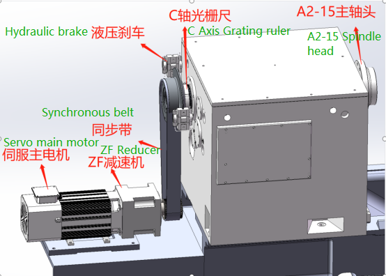
The spindle box adopts a threaded form and a single spindle structure, combined with a German ZF reducer, which can achieve maximum and low gear shifts, meeting the needs of high-speed precision turning and low-speed re cutting of the workpiece, with a high rotational speed of up to 360r/min; The maximum spindle torque in low gear can reach 5500N. m, and the maximum torque in high gear is not less than 1000N. m.
Equipped with BMT85 power turret with Y-axis; Power turret drive motor 7.5Kw/3000r/min, Y-axis travel 200mm (± 100mm)
The tailstock movement and tailstock sleeve movement are motorized, with internal disc springs and hydraulic cylinder devices, which can preset the tightening force in advance by adjusting the pressure;
The sleeve is tightened automatically, and the tailstock is locked manually;
The large walking platform and hanging button station move along the direction of the bed with the knife tower, making it easy to operate.
2.Main Parameters of machine :
Item | Unit | Parameters | |
Parameters | Max. Turning workpiece diameter | mm | Φ1100 |
Min. Turning workpiece diameter | mm | Φ150 | |
Distance between two centers | mm | 10000 | |
Max.workpiece Length | mm | 10000 | |
Width of guide rail | mm | 1615 | |
Max. Loading weight between two centers | ton | 20 | |
Spindle | Diameter of spindle front support bearing | mm | Φ220 |
Taper of spindle inner hole | Metric Φ140 | ||
Angle of center | degree | 60 | |
Spindle head form | A2-15 | ||
Spindle rotation speed range | r/min | 15-360 (Automatic two-gear) | |
Main motor power | kW | AC38 | |
Chuck diameter of spindle | mm | Φ1000 | |
Max. Torque of chuck | kN.m | 46 | |
Tool turret | Feed motor torque (X/Y/Z) | N.m | 30/30/50 |
Rapid move speed of feed axis(X/Y/Z) | m/min | X∶4/Y:4/ Z∶4 | |
Max. stroke of X axis | mm | 525 | |
Max. stroke of Z axis | mm | 10000 | |
Turret interface | mm | BMT85 | |
Turret driving motor | KW | 12 | |
Cutting tool section size | mm | 32 x 32 | |
Frame type tool turret | Power turret | ||
Tailstock | Sleeve diameter | mm | Φ280 |
Max. Stroke of sleeve | mm | 300 | |
Sleeve moving speed | mm/min | 50 | |
Mandrel taper hole | mm | Morse 6#,φ80 | |
Center angle | degree | 60、75 | |
Move speed of tailstock | mm/min | 2000 | |
Hydraulic center frame (Germany SMW) | Clamping range | mm | 125-460 |
Working pressure | Mpa | 0.8-7 | |
Centering precision | mm | 0.06 | |
Repeatability | mm | 0.01 | |
Others | Dimension(LxWxH) | mm | 14500×3700×3200 |
Machine total weight | kg | 48000 | |
Machine total power | KVA | 150 | |
Machine accuracy | Roundness of fine turning outer circle | mm | 0.008 |
Cylindricity of fine turning outer circle | mm | 0.04/300 | |
Flatness of fine turning end face | mm | 0.02(100 Testing length) | |
Processing accuracy | IT6 | ||
Surface roughness of fine turning outer circle | μm | Ra1.6(Standard test job ) | |
Fine turning outer circle Surface roughness | μm | 0.8(HRC42 or above workpiece hard turning) | |
Machine noise | DB(A) | 85 | |
Infeed axis Repeatability (X/Z) | mm | X:0.01 Z:0.016/2000 | |
Infeed axis Positioning accuracy (X/Z) | mm | X:0.02 Z:0.04/2000 | |
3.Machine main parts :
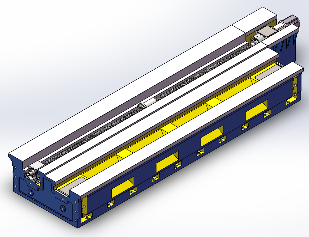
3.1Machine bed :
The machine bed is cast by high-strength cast iron and resin sand, resin sand molding ; The bed is an integral four-guide rail structure, which has good anti-subversion performance when supporting the workpiece. The cross section of the bed is guided by three rectangular guide rails, which are used for the longitudinal movement of the sliding box and tailstock. The bed is the basic part of the machine , and its rigidity directly affects the working performance and accuracy of the whole machine . The bed of this machine adopts resin sand molding and cast with high-quality cast iron. It has good appearance and strength. The layout of reinforced ribs is reasonable, and has excellent anti-section distortion ability, which effectively improves the anti-vibration performance of the machine . The chips removal hole is set on the side of the machine, which has good chips removal ability. The sliding surface of the bed saddle is pasted with wear-resistant materials, which not only reduces friction, but also improves the service life of the machine. In order to further reduce the impact of cutting overturning moment on the machine and ensure the operation accuracy, the whole length of the machine body is supported on several adjustable sizing blocks and fastened with foundation screws, which increases the contact area between the machine body and the foundation, and improves the retention of the machine body accuracy.
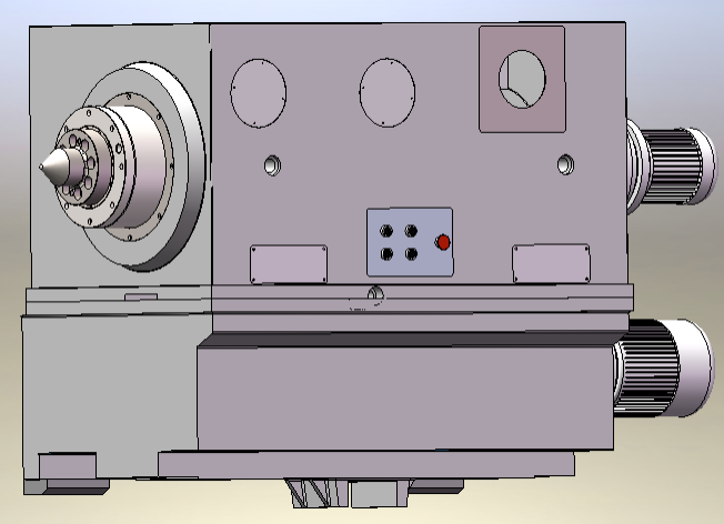
3.2Headstock
The spindle box hs an independent hydraulic control system and lubrication system. The spindle box handle is attached to the base, and the base is attached to the bed handle. The spindle bearings are selected from domestic and foreign famous and high-quality bearings, with strong spindle rigidity and high rotation accuracy.
The main transmission adopts a special design. The spindle box adopts a threaded form and a single spindle structure, combined with a German ZF reducer, which can achieve maximum and low gear shifts, meeting the needs of high-speed precision turning and low-speed re cutting of the workpiece, with a high rotational speed of up to 360r/min; The maximum spindle torque in low gear can reach 5500N. m, and the maximum torque in high gear is not less than 1000N. m.
3.3Tailstock (sketch 3):
The tailstock adopts upper and lower split structure. The lower body is equipped with a tailstock fast moving mechanism, a stop mechanism and oil pump etc. . Inside of the tailstock upper body ,the front end of tailstock sleeve main spindle is supported on double row radial roller bearing, same with spindle structure , has high rigidity . The rear end of the tailstock main spindle is equipped with a dish spring that can prevent the mechanism from being damaged due to thermal expansion of the workpiece, and equipped with hydraulic force measuring device. The center is a flange type short taper handle center. A pressure gauge is set at the front and back of the tailstock, the pointer position can be set according to the weight and the tightening force label.
The rapid movement of tailstock and tailstock sleeve is driven by separate motor and equipped with overload protector. It should be noted that the tailstock stop plate must be withdrawn before starting the tailstock fast moving motor. A oil pump is installed at the rear end of the lower body of the tailstock to supply lubricating oil for all mechanisms in the tailstock. The guide rail surface for movement of tailstock is
inlaid with wear-resistant materials, which can reduce the wear of the guide rail of the bed.

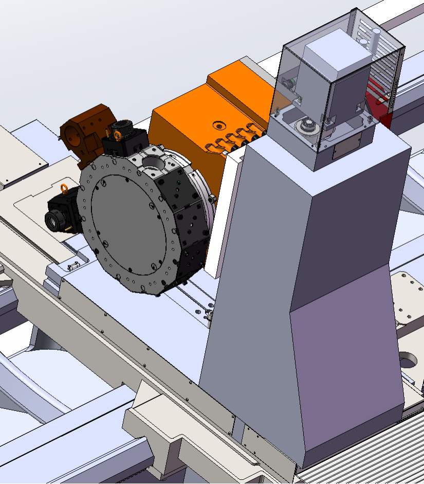
3.4Tool turret
Equipped with BMT85 power turret with Y-axis; Power turret drive motor 7.5Kw/3000r/min, Y-axis travel 200mm (± 100mm); Cooperating with the equipment spindle (C-axis), it can achieve machining functions such as workpiece outer circle, end face drilling, milling, and turning in combination;
The Z-axis, Y-axis, and X-axis of the tool holder are all driven by AC servo motors and driven by a reducer. The ball screws in both the Y-axis and X-axis directions are installed in the middle of the guide rail, which has the advantages of stable guidance, no tilting torque, good accuracy retention, and long service life. The Z-axis adopts a precision helical rack drive and a precision reducer deceleration structure.
3.5 Safety guard:
The X and Z directions of the tool turret are equipped with stainless steel telescopic guide rail protective cover, and the foundation protection fence is placed at side of the tailstock to ensure the safety of the operator .
3.6 Cooling device :
The machine is equipped with cooling device, and the cooling mode is water cooling. The cooling nozzle is installed on the upper part of the tool turret. The cooling water is delivered to the cooling nozzle through the water pump, and then flows into the water tank by gravity through the chips removal hole and enters the recirculation system after filtration.
3.7 Electric system :
The machine is equipped with SIEMENS 828D CNC system , the elctric cabinet adopts American Rittal structure , has nice appearance and good sealing ,equips with air-conditioner to ensure all the electric components working under a reasonable temperature ,to improve service life of machine.
3.8 Other special accessories
The equipment is equipped with an automatic chip conveyor with a chip trolleyEquipped with a high-pressure cooling pump, the coolant pressure can reach up to 60 bar, and equipped with a cleaning water gun;
The equipment is equipped with an online measurement device for workpiece, which can detect the turning dimensions of the outer circle, end face, etc. of the workpiece in real-time;
The equipment is equipped with a tool alignment instrument, which can automatically detect the condition of the cutting tools;
Equipment selection φ140mm Boring tool holder device for reference hole;
Two sets of hydraulic center frames for the equipment, with a clamping range φ 125-460mm;
Equipment equipped with electric box air conditionor.
The equipment is equipped with a fixed C-shaped roller rack with 20-370mm -1 pieces;
The equipment is equipped with a fixed C-shaped roller rack 290-500mm-1 pieces;
Ring bracket with independent jaws Ø 80-450mm---1 piece
4. Machine tool working conditions
4.1 The entire machine adopts three-phase AC: (380V ± 10%; 50Hz ± 1 Hz) unified power supply.
4.2 Work area lighting (voltage, power): 220V, 300W/500W
4.3 Machine tool operating environment temperature: 5 ℃~40 ℃
4.4 Environmental relative humidity: ≤ 85%
4.5 Workshop free from harmful gases, liquids, and dust
5.Main parts list :
NO | Name | QTY | Application |
1 | Precision bearing | 1set | Spindle bearing |
2 | Precision bearing | 1set | Tailstock mandrel |
3 | Ball screw | 1set | X-axis:6312 Z-axis:6312 |
4 | CNC system | 1set | Dual channel |
5 | AC servo motor | 1set | X-axis、Y -axis、Z-axis |
6 | Feeding drive system | 1set | X-axis、Y -axis、Z-axis |
7 | Main motor | 1set | Main drive |
8 | Turret driving motor | 1set | Power turret |
9 | Guide rail protective cover | 1set | X-axis、Z-axis |
10 | Electric cabinet | 1set | |
11 | Mainly hydraulic components | 1set | |
12 | Spindle precison reducer | 1set | |
13 | BMT 85 Power turret | 1set | |
14 | C axis encoder | 1set | |
15 | Manual four jaw chuck | 1set | Φ1000 |
16 | Manual 3 jaw self-centering chuck | 1set | Φ500 |
2. Standard configurations:
NO | Item | QTY |
1 | Machine bed | 1SET |
2 | Spindle box | 1SET |
3 | Y axis Tool turret | 1SET |
4 | Tailstock | 1SET |
5 | Hydraulic,Lubrication device | 1SET |
6 | Chain device | 1SET |
7 | Spindle tailstock centres | 1SET |
8 | Button station | 1SET |
9 | Electric cabinet | 1SET |
10 | Automatic chip conveyor | 1SET |
11 | Motor driving system | 1SET |
12 | Automatic lubrication system | 1SET |
13 | Hydraulic center frame | 2SETS |
14 | Machine tool Kit | 1SET |
Product Parameters:

Whatsapp Code


 +86-151 6596 4868
 +86-151 6596 4868
 +86-151 6596 4868
 susan@novatechlathe.com
