



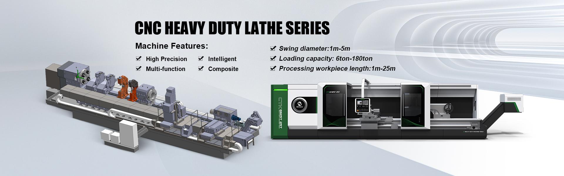
Product Features:
1、Product Model and Name
CXK61200 CNC Horizontal Crankshaft Turning-Milling Machine
This machine tool is a high-precision and high-efficiency CNC machine tool developed mainly for the processing of crankshaft connecting rod journals and main journals in the industry. It drives and clamps the crankshaft to rotate through the eccentric fixtures installed on the spindle chuck and tailstock chuck. A rigid integral circular milling cutter head is used to complete the rough machining of crankshaft journals, fillets, shoulder sides, undercut grooves and web surfaces, followed by turning for finishing.
This machine tool is a CNC horizontal crankshaft turning-milling machine developed by our company, with the following features: The main transmission and feed transmission adopt a separate type. It uses the Beijing KND2000T CNC system, and each of the two tool rests is equipped with a set of display screens. The X-axis and Z-axis are configured with linear gratings to realize full closed-loop control. The bed adopts an integral three-guide-rail structure. The spindle of the headstock is in the form of a through shaft with two supports, and the maximum speed can reach 200 r/min. It is equipped with a frame-type tool rest, main and auxiliary tool plates; the tailstock movement and tailstock sleeve movement adopt a motorized mode; the tailstock locking adopts a manual mode; the sleeve locking adopts a disc spring clamping and hydraulic releasing structure; it is equipped with a platform and a suspended button station for convenient operation.
The machine tool is equipped with a C-axis box, and the transmission adopts a double-motor anti-backlash form, which can participate in interpolation. The machine tool is configured with two tool rests: the front one is a turning tool rest; the rear one is a milling tool rest. Both the turning tool rest and the milling tool rest can machine the full length of the crankshaft.
No. | Name | Indicator | |
1) | Power supply | Voltage | 380V±10% |
2) | Frequency | 50HZ±2% | |
3) | Ambient temperature | 5~40℃ | |
4) | Relative humidity | ≤92% | |
5) | Compressed air | 0.4~0.6MPa | |
Maximum swing diameter over bed | mm | Φ2000 |
Maximum turning diameter over carriage | mm | Φ1600 |
Maximum workpiece length between centers | mm | 6000 |
Maximum crankshaft length | mm | 3000 |
Maximum crankshaft weight | t | 5 |
Bed width | mm | 1850 |
Spindle speed range | r/min | 1-200 |
Number of spindle speed stages | stage | Mechanical two-speed transmission, with continuous gear change within each gear. |
Diameter of spindle front bearing | mm | Φ320 |
Tip size and angle | Short cone | 1:4 φ100mm 75° |
Spindle drive motor | kW | AC 75 (Spindle Servo) |
Maximum spindle torque | kNm | 50 |
Spindle chuck diameter | mm | φ1600 |
1:30 | ||
C-axis speed range | r/min | 0.1-2 |
C-axis drive mode | Dual-motor leveling mechanism |
Milling spindle speed range | r/min | 30-45 |
Milling spindle speed change levels | stage | stepless |
Milling cutter disc diameter | mm | φ1200mm |
Milling spindle drive motor | kW | AC 30 (Spindle Servo) |
Milling spindle maximum torque | Nm | 4000 |
Z-axis (distance of longitudinal movement of the front and rear tool holders) | mm | >3000 |
X-axis (distance of lateral movement of the lateral slide) | mm | 700 |
Type of tool holder | Frame-type tool rest | |
Maximum cutting force of the tool holder | kN | 50 |
Feed rate in the longitudinal and lateral directions | Continuous adjustment | |
Range of feed rate in the longitudinal and lateral directions | mm/min | 0.1-1000 |
Fast movement Z/X | mm/min | 4000 |
Drive motor Z-axis | Nm | 50 |
X-axis | Nm | 30 |
System minimum setting unit Z/X | mm | 0.001 |
Tailstock sleeve diameter | mm | Φ320 |
Tailstock sleeve movement distance | mm | 300 |
Tailstock center rest (built-in live center rest) | Short cone | 1:4 φ100mm 75° |
Tailstock sleeve movement mode | Mobility | |
Tailstock movement mode | Mobility | |
Sleeve movement speed | mm | 50 |
Tailstock rapid movement speed | mm/min | 2000 |
mm | Φ1250 |
Center support range | mm | Φ250-φ350 2 set | Tentative |
Radial runout of the spindle (at the root) ≤0.015mm
The distance from the main shaft end face should not exceed 500mm. ≤0.040mm
Axial runout of the spindle axis ≤ 0.015mm
The radial runout of the spindle nosepiece ≤0.020mm
The radial runout of the tailstock center. ≤0.020mm
X-axis positioning accuracy 0.02mm
X-axis repeatability positioning accuracy 0.01mm
Z-axis positioning accuracy 0.02mm/1000mm
Z-axis repeatability positioning accuracy 0.01mm/1000mm
5.2 Work accuracy (standard specimen)
Roundness ≤0.012mm
Cylindricity ≤0.035/500mm
The flatness of the precisely machined surface: ≤0.025/300mm gage length
Surface Roughness (Standard Specimen): Outer Circle Ra1.6, Conical and Arc Surfaces Ra3.2
This machine tool's accuracy complies with the national standard GB/T23569 of the People's Republic of China, "Precision Inspection of Heavy-duty Horizontal Lathe". Since the processing accuracy of crankshaft parts involves many factors, therefore this accuracy does not represent the final processing accuracy of the crankshaft workpiece.
This machine tool is mainly composed of the bed, the headstock, the C-axis feed box, the headstock base, the main motor and the motor base, the main spindle chuck, the center rest, the tailstock, the tailstock chuck, the eccentric fixture, the tool holder, the milling power head, the walkway, the hydraulic system, the electrical system, the numerical control system and the random accessories.
The bed of this machine tool is made of high-strength cast iron and is shaped using resin sand casting technology. The bed is an integral three-guide rail structure. When supporting the workpiece, the bed has excellent anti-overturning performance. The main guide rails of the bed are treated with medium-frequency quenching, with a hardness of no less than HRC50 (a soft band for process quenching is left in the middle of the guide rails), which significantly improves the wear resistance of the bed.
The bed is the basic component of a machine tool, and its rigidity directly affects the working performance and accuracy of the entire machine tool.
This machine tool's bed is made using resin sand molding and is cast from high-quality cast iron. It has excellent appearance and strength. In terms of structure, the layout of the ribs and plates is reasonable, which has excellent resistance to surface distortion and increases the overall damping of the bed, effectively improving the machine tool's vibration resistance. The chip removal holes are set at the bottom of the machine tool, which has good chip removal capability. The sliding surface of the saddle is coated with wear-resistant materials, which not only reduces friction but also extends the service life of the machine tool.
To further reduce the influence of the cutting overturning moment on the machine tool and ensure the running accuracy, the bed body is fully supported on several adjustment pads and is tightened with anchor bolts, thereby increasing the contact area between the bed body and the foundation and improving the maintainability of the machine tool bed body's accuracy.
The leading guide rail adopts a V-shaped guide rail, which has good guiding performance. The tailstock guide rail and positioning guide rail adopt a mountain-shaped guide rail, and the tailstock movement accuracy is high.
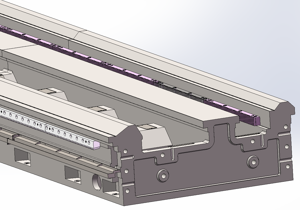
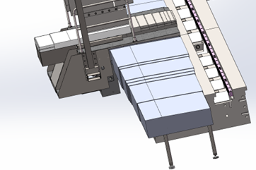
Overall three-guide rail bed body
The spindle box has an independent hydraulic control system and lubrication system. The spindle box is fixed to the base, and the base is integrated with the bed. The spindle bearings of the machine tool are selected from renowned brands, with strong rigidity and high rotational accuracy. The spindle taper pin is a flange-type short taper pin, with a taper surface for positioning, and is fixed to the spindle by screws, enhancing the connection stiffness between the taper pin and the spindle.
The main drive adopts an AC spindle servo motor drive, installation type B3, mechanical speed regulation with two levels, speed ratio 1:4, enabling the spindle to achieve a rotational speed range of 1 - 200 r/min. The secondary mechanical speed change of the spindle box is realized by electromagnetic solenoid valves - oil cylinders. Each side of the spindle box is equipped with a button station, allowing for the control of forward and reverse point motion, continuous operation, and stop of the spindle.
A flow sensor is installed in the recess on the rear wall of the spindle box. It will give an alarm when the lubrication volume is too low. An encoder is added at the rear end of the spindle to achieve thread cutting.
The chuck is made of ZG310-570 cast steel. It is combined with the spindle through a 1:30 conical surface interference fit, and is integrated with the spindle. It has reliable self-deformation resistance and connection rigidity.
When used as a heavy-duty horizontal lathe, this machine adopts heavy-duty clamps and mechanical jaws. Using a special wrench and the two gear plates on the jaw body, it achieves force amplification for clamping the workpiece, significantly reducing the labor intensity of the workers and improving efficiency.
When processing crankshafts, an eccentric fixture is installed on the chuck to clamp the workpiece and perform indexing.
A hydraulic damping and braking device is installed on the outer side of the chuck
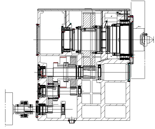
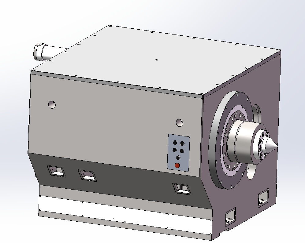
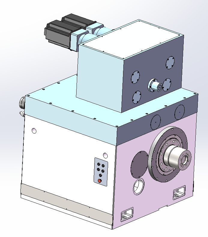
Structural diagram of the main shaft box of heavy machine tools
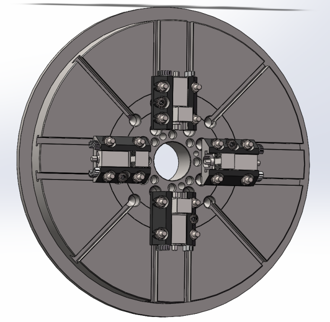
Chuck structure diagram
The tailstock adopts an upper-lower split structure. Inside the lower part, there is a tailstock rapid movement mechanism, tailstock clamping mechanism, lubrication device, hydraulic device, etc. On the upper part of the tailstock, the front end of the tailstock sleeve main shaft is supported on a double-row radial roller bearing, which is similar to the main shaft structure and has high rigidity. The rear end of the tailstock main shaft is equipped with a disc-shaped spring to prevent damage to the mechanism due to the thermal expansion of the workpiece, ensuring that the deformation of the workpiece does not cause changes in the tailstock main shaft during processing. The configuration includes a sleeve motor-driven moving mechanism, sleeve locking and releasing mechanism, and hydraulic force measurement device. The tailstock is a flange-type short taper pin tailstock. At the front and rear of the tailstock, there is a pressure gauge on each side, and workers can select and set the appropriate pointer position according to the tightening force marking of the workpiece based on its weight.
The outer surface of the tailstock is equipped with tightening force calculation plates for using different angle tailstocks and processing different workpiece tonnages.
The rapid movement of the tailstock and the tailstock sleeve have separate electric motors for driving, and overload protection is provided. The tailstock movement uses a gear-rack transmission method, which is stable and reliable. After moving to the position, the gear plate and the pressing plate are manually locked. The guide surface is coated with wear-resistant material, which can effectively reduce the wear on the bed guideways.
The tailstock movement has overload protection and reliable limit positioning.
Tailstock with chuck.
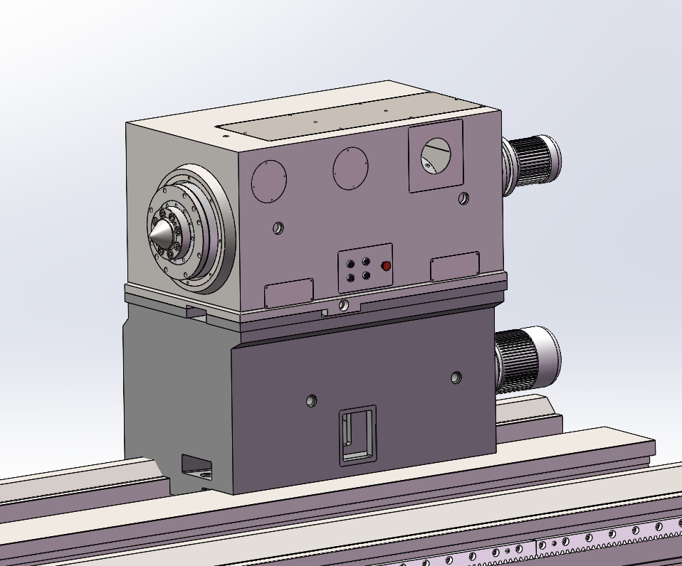
Tailstock Diagram
The turning tool rest adopts a frame-type tool rest, which is suitable for heavy-duty horizontal lathes. It is used for rough and fine processing of various shaft parts, especially for heavy cutting (rough processing) and the processing of stepped shafts, deep slots, and end faces. The tool plate is divided into the main and auxiliary tool plates, which are configured on the two sides of the tool rest body and can be independently extended and retracted. They are fixed on the tool rest body with a press plate and the extension length of the tool plate can be determined according to needs. The tool plate moving mechanism is operated manually.
The tool rest is composed of a large slide plate and an upper tool rest and is integrated as a whole. The longitudinal movement of the tool rest is a double-gear - rack backlash elimination structure with strong transmission rigidity. The feed box is integrated with the large slide plate. It is driven by a servo motor and the reduction mechanism outputs the motion to the gears and racks, which then transmits the motion to the slide plate. This ensures the transmission accuracy and improves the承载 capacity.
The Z-axis and X-axis of the tool rest are all driven by AC servo motors. The lateral movement of the tool rest is 4000mm/min, the feed is 1-1000mm/min, and the longitudinal movement is 4000mm/min, the feed is 1-1000mm/min. The upper body of the large tool rest frame adopts a left-right frame-type double-sided tool plate structure, which is more rigid than the traditional tool rest and is suitable for heavy cutting. The movement of the main and auxiliary tool plates is manual, and they are clamped manually after reaching the position. The movement is convenient and the clamping is reliable.
Walkways are set on both sides of the tool rest, both of which have upper and lower steps. The operation panel can rotate and move, which is convenient for operation.
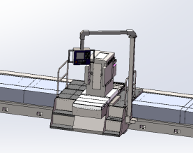
Diagram of the tool holder
The fixture is equipped with a rear counterweight mechanism on the main shaft. A counterweight disc mechanism is installed behind the main and auxiliary shaft boxes, which is convenient for the counterweight requirements of large crankshaft workpieces. The front fixture can be adjusted in the eccentric distance direction, enabling the processing of multiple series of crankshafts. The part of the crankshaft that holds the bearing shells is replaced with bearing shells according to the size of the crankshaft end. For the indexing of large crankshafts, the cooperation of the workshop crane is required. On the end face of the crankshaft bearing shell fixture, there is a scale plate to indicate the rotation angle.
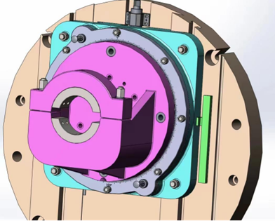
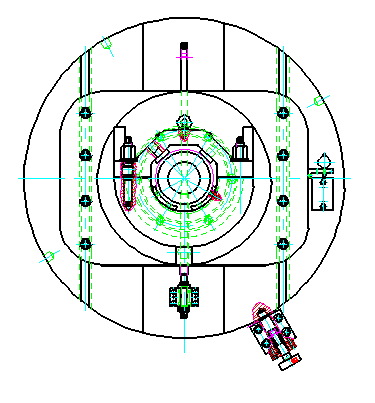
Illustration of the fixture (The specific structure of the fixture can be specially customized according to the user's requirements. Both parties will negotiate the structure and confirm it.)
The rear tool rest is a special tool rest designed for crankshaft milling. It consists of a milling head, a slide plate, a drag plate, and a two-axis feed system.
The milling head is a power component. It uses multi-stage gear reduction to transfer the power from the spindle servo motor to the dedicated milling cutter disc. The milling spindle speed range is 30-45 r/min, and the spindle servo motor has a power of 30 kW. The milling cutter disc uses a direct cutting method to process the crankshaft, and multiple cuts are made to complete one diameter processing.
The milling cutter disc is in a combined form, which is convenient for later maintenance and replacement.
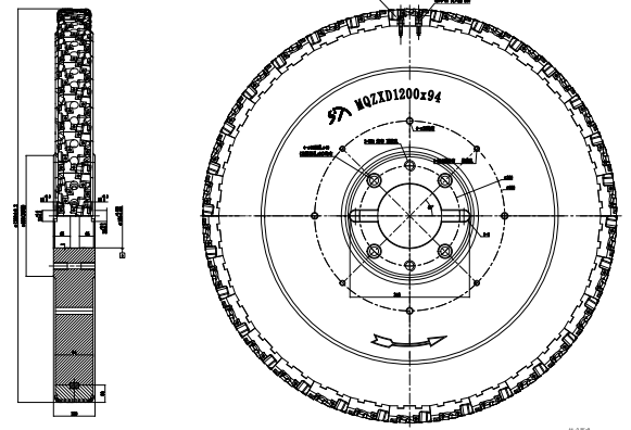
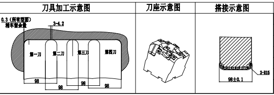
Structure and processing schematic diagram of the special milling cutter disc for crankshaft (tentative)
Crankshaft milling cutter cutting parameters
1) Blade: Coated
2) Cutting method: Dry cutting
3) Processing type: Rough machining
4) Cutting parameters as follows:
(1) Linear speed: 140 - 150 m/min;
(2) Feed per tooth: fz = 0.2 - 0.3 mm/z
(3) Cutting depth: ap = 4 - 8 mm
Take the processing of one crankshaft for a 5-cylinder pump as an example:
Diameter: Φ250mm
Width: 290mm
Processing amount: 10mm, divided into 2 passes to reach the quantity.
C-axis rotational speed: 2.5 min/r
Total time for one pass of processing, divided into 4 cuts: 2.5 min/r x 4 = 10 min
Total processing time for one crankshaft: 10 min x 2 = 20 min
This machine tool is equipped with two sets of center rests (the quantity and range can be increased according to the user's requirements). The center rests are in the form of sliders; they are manual gear-rack type and are only for adjustment purposes. All the center rests can be manually moved longitudinally along the bed.
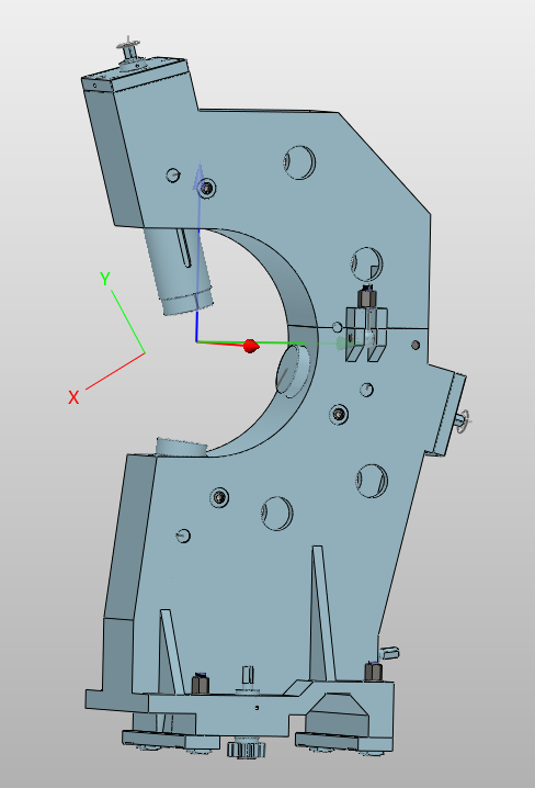
Center frame diagram
Each part of the machine tool is equipped with an independent lubrication system. The hydraulic system is divided into two major parts: the headstock hydraulic system and the tailstock hydraulic system. The headstock hydraulic system mainly functions to lubricate various bearings and gears in the headstock and to operate the shift cylinder of the headstock. The tailstock hydraulic system mainly serves to release and clamp the tailstock sleeve.
The X-axis and Z-axis guide rails of the tool holder are equipped with stainless steel telescopic guard covers.
The control station is fixed on the carriage. It has an operation panel and a numerical control control panel.
The work lights are installed on the top of the tool holder.
The turning tool rest is equipped with a tool cooling system (coolant), which can effectively reduce the temperature of the cutting area during the turning process, extend the tool life, and improve the processing accuracy.
The milling tool rest uses a compressed air air-cooling method to cool the cutting area, thereby increasing the tool life.
The spindle servo motor and driver adopt domestic systems, while the numerical control system uses the Beijing KND2000T system. The electrical design of the machine tool complies with the GB 5226.1-2008 electrical standard. The power circuits of the machine all have overcurrent and short-circuit protection, and there are corresponding interlocks for the related actions of the machine tool to ensure the safety of the equipment and personnel. The electrical system has self-diagnosis function. Operators and maintenance personnel can observe the operation status of each part of the machine tool at any time through indicator lights and displays. The main electrical components are selected from imported products, and other electrical components are selected from products of domestic and foreign cooperation, thus ensuring the safety and reliability of the machine tool.
1)Electrical box
A closed-type electrical box is adopted. The box is cooled by an air conditioner to ensure the normal operation of electrical equipment. The box adopts a trough-board wiring structure, with reasonable, neat and attractive layout of components and wiring, facilitating maintenance. The box is equipped with internal lighting and debugging sockets. A certain amount of space is reserved inside the box to facilitate the expansion of functions.
2)Machine tool operation control box
Use a suspended or tabletop control box. Equipped with a suspended handheld pulse generator, which is convenient for setting up and operating the machine tool.
3) Safety Protection
The machine tool is equipped with an alarm device and an emergency stop button, which can prevent various unexpected faults from causing damage to the machine tool. Due to the reasonable design of the software, the alarms can be displayed on the monitor in the form of text and alarm numbers. The machine tool classifies the handling methods of alarms according to different situations into three categories: for emergency alarms, an "emergency stop" is implemented; for general alarms, "feed retention" is adopted; for operational errors, only "prompting" is carried out.
No. | Name | Quantity | Purpose | Manufacturer |
1 | Spindle precision bearing | 1 Set | Spindle box | NSK |
2 | Tail shaft precision bearing | 1 Set | Tailstock | NSK |
3 | Other bearings | 1 Set | Domestic renowned products | |
4 | Ball screw | 1 Set | X-axis | Taiwan |
5 | Control system | 2 Set | Tool rest | Beijing KND2000T Siemens |
6 | Servo motor for communication | 2 Set | X, Z axis | Siemens |
7 | Feed drive system | 2 Set | X, Z axis | Siemens |
8 | Spindle motor driver | 2 Set | Main drive | Siemens |
9 | AC spindle servo motor | 2 Set | Main drive | Siemens |
10 | Electrical control cabinet | 2 Set | Control system | Domestic renowned brands |
11 | Electrical control cabinet air conditioner | 1 Set | Leibo or Tongfei | |
12 | Main electrical components | 1 Set | Electrical control cabinet | Suzhou Siemens / Schneider |
13 | Main hydraulic components | 1 Set | Domestic premium brands | |
14 | X-axis precision planetary reducer | 1 Set | X-axis | Newstart or equivalent brands |
15 | Z-axis precision planetary reducer | 1 Set | Z-axis | Newstart or equivalent brands |
No. | Project name | Quantity | Remark |
1 | lathe bed | 1 Set | |
2 | Headstock | 1 Set | |
3 | Chuck | 1 Set | |
4 | Headstock base | 1 Set | |
5 | Tailstock | 1 Set | |
6 | Feed box | 1 Set | |
7 | Turning tool rest | 1 Set | |
8 | Milling tool rest | 1 Set | |
9 | Special milling disc for crankshaft | 1 Set | Tentative |
10 | Motor base | 1 Set | |
11 | Drainage chain device | 1 Set | |
12 | Foundation installation component | 1 Set | |
13 | Random tools | 1 Set | |
14 | Numerical control system | 2 Set | |
15 | Hydraulic control system | 1 Set | |
16 | Closed-type center rest | 2 Set | |
17 | Tool rest platform | 1 Set | |
18 | Random spare parts and accessories | 1 Set | |
19 | Tool cooling system of the lathe tool holder | 1 Set | |
20 | Air-cooling system of the milling tool holder | 1 Set | |
21 | Offset fixture for eccentric cutting of crankshaft bores | 2 Set | One set each for the left and the right. |
22 | Counterweight block | 2 Set | One set each for the left and the right. |
No. | Name | Model | Specification | Quantity | Purpose | Remark |
1 | Spindle end support | 75° | 1 | Spindle | ||
2 | Tail shaft end support | 75° | 1 | Tail shaft | ||
3 | Lifting pile | 01210 | 60-M60 | 4 | Spindle box | |
4 | Lifting pile | 01211 | 55-M42 | 8 | Tailstock, tailstock base | |
5 | Double-ended wrench | S91-1 | 22X24 | 1 | ||
6 | 41X46 | 1 | ||||
7 | Single-ended wrench | S91-2A | S=18 | 1 | ||
S=24 | 1 | |||||
S=36 | 1 | |||||
S=55 | 1 | |||||
8 | Square-head screwdriver | S92-5 | S=30 | 1 | 50 lead screw | |
9 | Hex key | S91-7 | S=4 | 1 | ||
S=5 | 1 | |||||
S=6 | 1 | |||||
S=8 | 1 | |||||
S=10 | 1 | |||||
S=17 | 1 | |||||
S=19 | 1 | |||||
S=22 | 1 | |||||
10 | Remove the oil gun | SYB-2 | 1 | Spindle chuck, spindle bearing | ||
11 | Wood-handled screwdriver | 12‘’ | 1 | |||
12 | Pressing knife screwdriver wrench | 1 |
No. | Name | Model | Specification | Quantity |
1 | Adjusting shims | S74-1 | ||
2 | Base bolts | GB799-88 | M30X1000 | |
3 | Hexagonal nuts | GB6170-86 | M30 | |
4 | Flat washers | GB97.1-85 | 30 | |
5 | Adjusting shim wrench | PS74-2 | ||
6 | Hexagonal socket wrench | CK61160G-01216 | ||
7 | Shim plate retaining ring | 01228 | ||
8 | Internal hexagonal screw | GB70-85 | M8x20 |
No. | Name | Specification | Material/Brand | Quantity |
1 | Y-shaped rubber gasket | G51-8 | 120 | 2 |
No. | Name | Content | Quantity |
1 | Packing List | 1 | |
2 | Certificate of Compliance | Including precision inspection sheet | 1 |
3 | User Manual | Involving mechanical and electrical aspects | 1 |
4 | Foundation condition diagram | 1 | |
5 | System manual | Usage, programming, maintenance, etc. | 1 |
6 | Main drive speed regulation system manual | 1 |
All of our products undergo a complete quality assurance system throughout the manufacturing process, including the procurement of raw materials and purchased components, part processing, inspection, and assembly and testing. We have obtained ISO9001 quality system certification and mainly comply with the following national standards:
GB/T9061-2006 General Technical Conditions for Metal Cutting Machines
GB 5226.1-2008 Mechanical Safety, Mechanical Electrical Equipment - Part 1: General Technical Requirements
GB/T23572-2009 General technical conditions for hydraulic systems of metal cutting machines
JB/T 4368.2-1996 Numerical Control Horizontal Lathe Parameters
JB/T 9874-1999 Metal Cutting Machine Tools - General Technical Conditions for Assembly
JB/T 9872-1999 Metal cutting machine tools - General technical conditions for mechanical processed parts
GB/T23569-2009《Inspection Conditions for Heavy Horizontal Lathe - Precision Inspection》
Product Parameters:

Whatsapp Code


 +86-151 6596 4868
 +86-151 6596 4868
 +86-151 6596 4868
 susan@novatechlathe.com
