



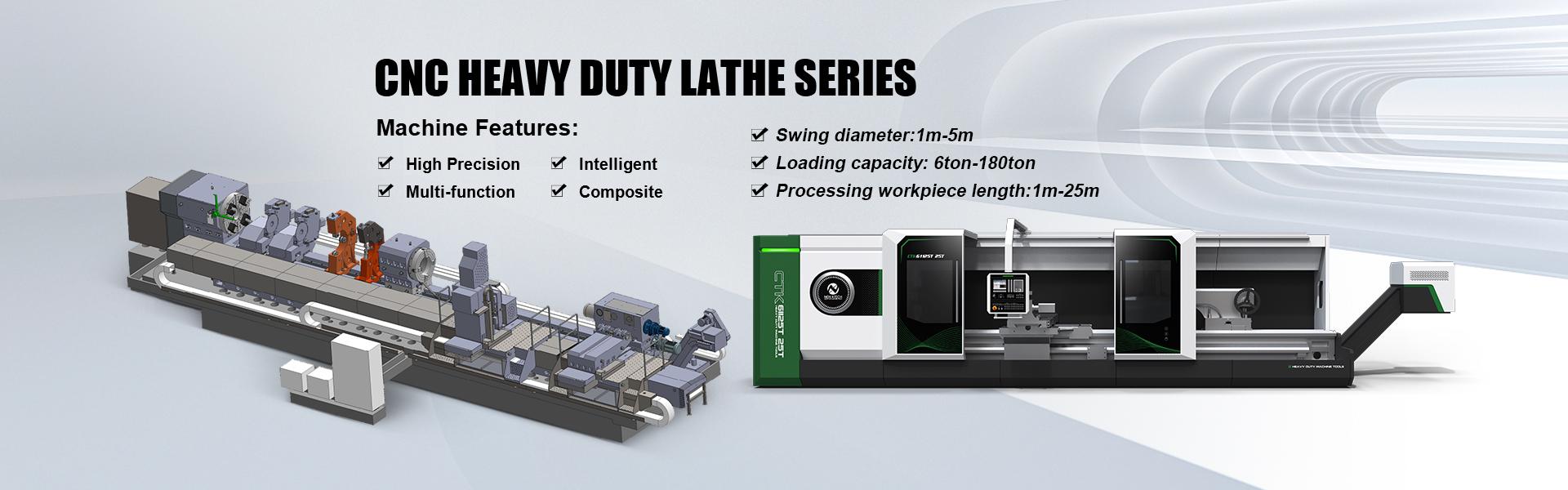
Product Features:
1.Product model and name
CTK61 T Series ×6-20M/25T CNC Heavy-duty Horizontal Turning Boring Lathe
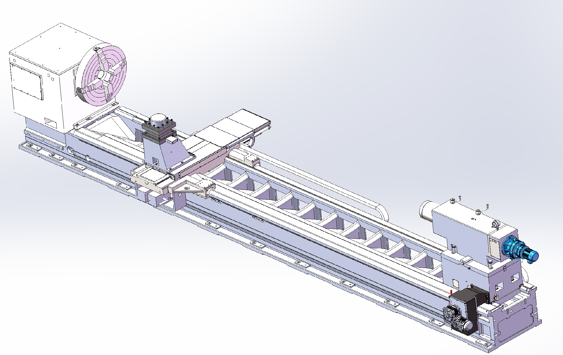
Schematic diagram of machine tool structure
2. Product Features
The machine consists of major components including the bed, headstock, carriage, tailstock, chuck, cooling system, hydraulic system, protective cover, and electrical system. It is capable of performing cutting operations such as external cylindrical surfaces, end faces, tapers, arcs, curved surfaces, grooves, and threads on shaft and disc-type workpieces.
This machine is a horizontal flat-bed CNC lathe controlled by the SIEMENS 828D CNC system, which comes standard with a portable handwheel for convenient tool setting and manual control.
The bed features a "one V, one flat + 45° hard rail auxiliary guideway" structure with medium-frequency hardened rail surfaces. The headstock employs a hydraulic four-speed gearbox. An electric 4-station tool turret is standard, while the tailstock adopts a split upper-lower structure. A semi-enclosed guard provides operator protection.The lateral transmission of the machine tool adopts servo motor and precision reducer combined with ball screw pair transmission, with semi closed loop control. The longitudinal transmission of the machine tool adopts a precision rack and double motor precision reducer double gear clearance structure, which realizes the longitudinal movement of the tool holder and semi closed loop control. The main motor can be driven by Sichuan EMK 37kW servo spindle motor.
3. Operating Environment
- Ambient temperature: 5°C to 45°C
- Relative humidity: ≤85%
- Power supply: 3-phase 380V±10%
- Power frequency: 50Hz±2Hz
Unit | Parameters | ||
Overall parameters | Maximum swing over bed | mm | Φ1250/1450/1650/1850/2050/2550 |
Maximum swing over carriage | mm | Φ830/1000/1200/1400/1600/2100 | |
Maximum workpiece length between centers | mm | 6000/7000/.../20000 | |
Machine guideway width | mm | 1350 | |
Maximum chuck/tailstock load capacity | Ton | 25 | |
Spindle | Front bearing diameter | mm | Φ280 |
Spindle bore taper | 1:4 φ80mm | ||
Center angle | Agree | 60° | |
Spindle nose type | Specification | 1:30 Long cone | |
Through hole diameter | mm | Solid shaft | |
Spindle speed range | r/min | 1-200 (Mechanical two gears) | |
Main motor power | kW | AC55(MK) | |
Chuck diameter | mm | Φ1000 Heavy duty manual four claw single action | |
Tool turret | X-axis travel | mm | 750/750/850/950/1050/1250 |
Z-axis travel | mm | 4850/5850/.../19850 | |
X-axis rapid traverse rate | mm/min | 4000 | |
Z-axis rapid traverse rate | mm/min | 4000 | |
X-axis feed motor torque | N.m | 27 SIEMENS | |
Z-axis feed motor torque | N.m | 48+48 SIEMENS Dual motor | |
Tool holder section size | mm | 40×40 | |
Turret specification | mm | 400×400 | |
Vertical 4-station turret brand | Changzhou | ||
Tailstock | Quill diameter | mm | Φ300 |
Maximum quill travel | mm | 300 | |
Quill movement speed | mm/min | 50 | |
Taper bore | mm | Metric 80 (with variable diameter sleeve) | |
Tailstock center | Mo's 6# | ||
Center angle | Agree | 60 | |
Tailstock overall movement | Electric | ||
Weight & Dimensions | Overall dimensions (L×W×H) | mm | 10500/11500/.../24500×3500×2300 (without length of chip conveyor) |
Machine total power | kVA | 80KW | |
Geometric Accuracy | X-axis repeat positioning accuracy | mm | ±0.012 |
Z-axis repeat positioning accuracy | mm | ±0.02/2000 | |
X-axis positioning accuracy | mm | ±0.02 | |
Z-axis positioning accuracy | mm | ±0.025/2000 | |
X-axis reverse deviation | mm | 0.01 | |
Z-axis reverse deviation | mm | 0.03/2000 | |
Machining Accuracy (GB standard test piece) | Dimensional accuracy | IT6-7 | |
Surface roughness | Ra1.6 Planar cylindrical surface | ||
Turned roundness | mm | 0.01 | |
Cylindricity | mm | 0.02/300 | |
Face flatness | mm | 0.025/300 | |
5.Introduction to Machine Tool Structure
5.1 Bed
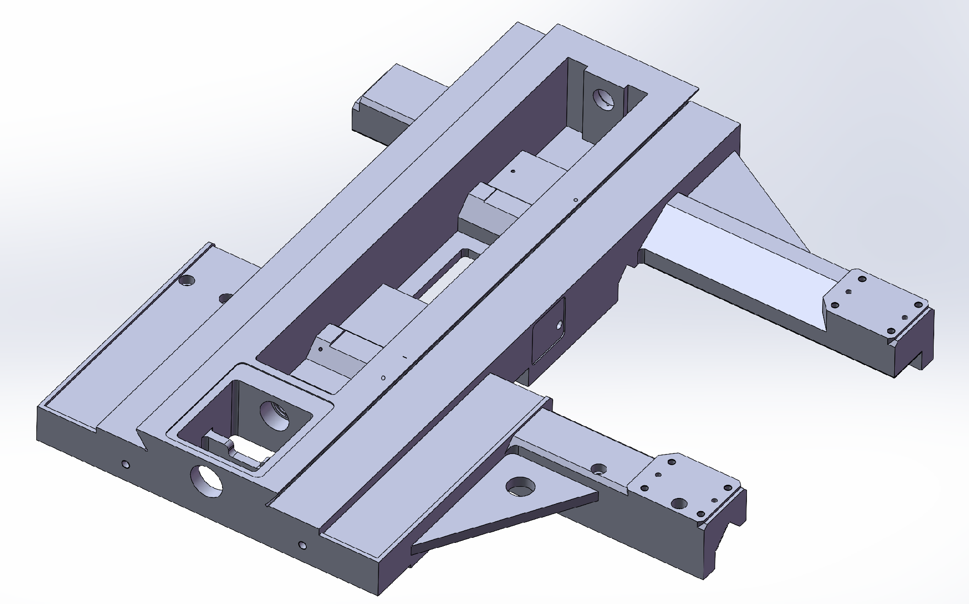
The machine bed is a floor-mounted type with a width of 1,350 mm. It is made of high-strength resin sand-cast HT300 material, offering excellent rigidity, high load capacity, and superior stability.
The guideways feature a "one V, one flat + 45° hard rail auxiliary guideway" structure, treated with medium-frequency quenching for deep hardness penetration, ensuring long-term durability and facilitating secondary regrinding.
Inside the bed cavity, "W"-shaped reinforcing ribs are integrated, connecting all surfaces into a unified structure. This design significantly enhances rigidity and minimizes deformation under load.
After aging treatment, the bed casting effectively eliminates internal residual stresses, reducing stress-induced deformation during machining and operation, thereby maintaining long-term precision.
The bed is designed with a rear chip evacuation slope and an arched opening, allowing chips, coolant, and lubricants to discharge directly into the chip pan. This ensures easy chip removal and enables coolant recycling for improved efficiency.
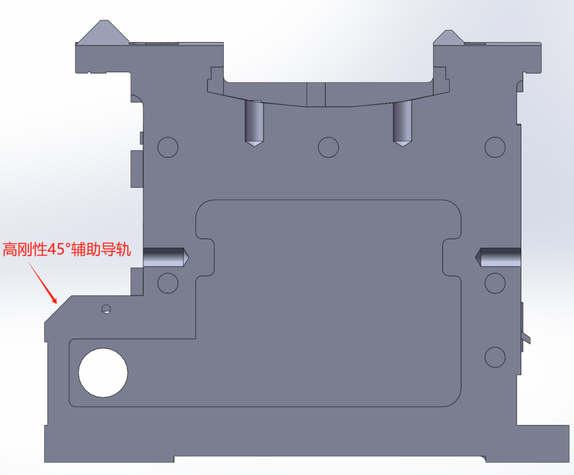
Bed section diagram
5.2 Headstock
The main spindle of the headstock adopts a classic and proven three-bearing support structure, utilizing high-precision spindle bearings from HRB,ZWZ brands. This ensures optimal rigidity, load capacity, smooth rotation, and high precision.
The main motor is a 55kW AC servo motor specifically designed for spindles, featuring high torque at low speeds. The spindle speed is four-range stepless variable, with a speed range of 1–200 r/min.
The headstock employs external circulation lubrication, where the lubricating oil is effectively cooled during the cycle. The lubrication pump is a gear pump, ensuring stable and reliable lubrication performance.
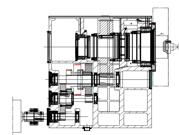
Spindle structure diagram
5.3 Carriage & Tool Turret
Employs a high-rigidity heavy-duty carriage structure designed for integrated turning and boring operations.
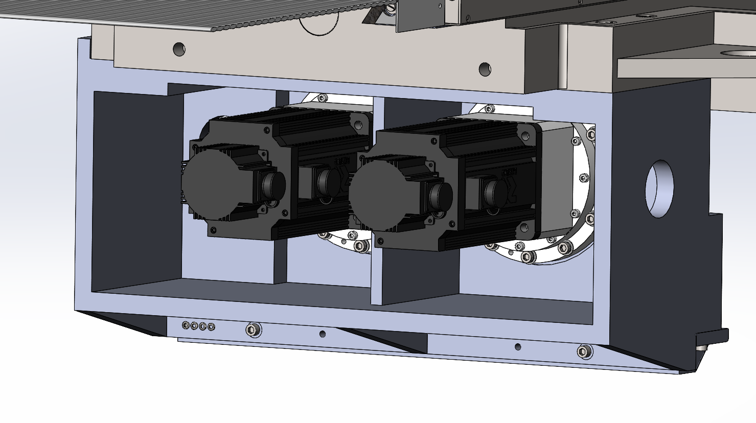
The carriage transverse motion utilizes a ball screw drive. The ball screw is supported by domestically manufactured 60° angular contact ball screw bearings (P4 grade) in a back-to-back arrangement, forming a "fixed-tensioned" support configuration. Pre-tensioning ensures exceptional precision and axial rigidity.
Z-axis precision rack and double motor precision reducer with double gear clearance structure, realizing longitudinal movement of the tool holder. After adding a grating ruler, it forms a fully closed-loop control, with smooth transmission and high load-bearing capacity.
Tool turret equipped with an electric vertical 4-station indexing tool turret, featuring smooth indexing, reliable positioning, and user-friendly operation.
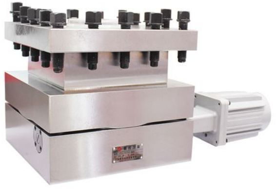
Diagram of tool turret
5.4 Tailstock:
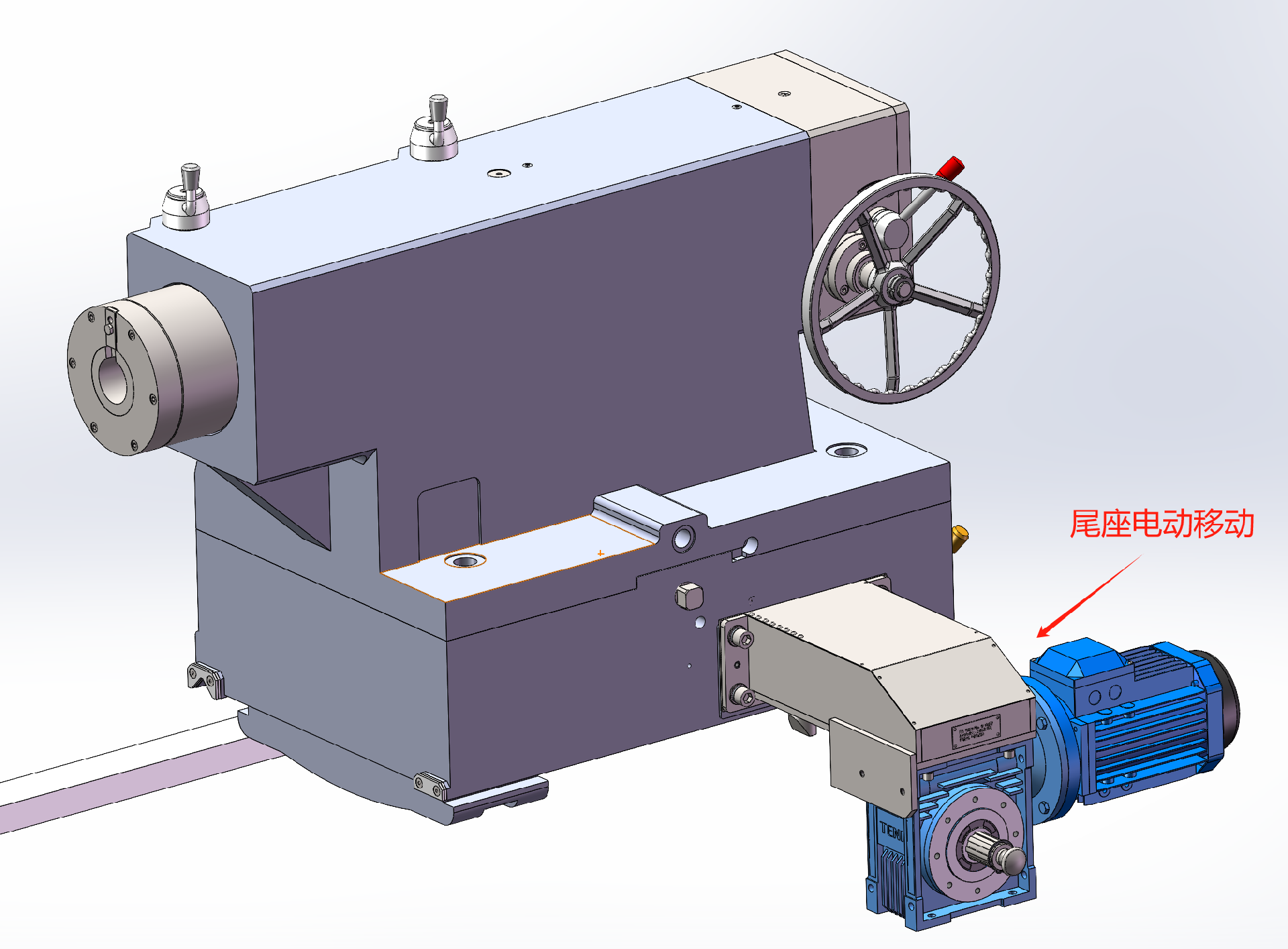
The tailstock of this machine tool is a core shaft rotating structure, with a tailshaft sleeve diameter of up to 300mm, providing sufficient rigidity and load-bearing capacity. The movement of the tailstock is driven longitudinally by an AC motor through gears and racks, making it convenient, fast, and pleasant to move. The tailstock sleeve is driven by an AC motor through a needle wheel reducer and a T-shaped screw, which can easily tighten and loosen the workpiece, making it more comfortable. The tailstock consists of two main parts: the upper and lower parts. The upper part of the tailstock is equipped with a tailstock sleeve, a core shaft, a tailstock sleeve moving mechanism, and a spindle center adjustment mechanism. The tailstock spindle bearing adopts high-precision spindle special bearings from HRB / ZWZ / LYC with strong load-bearing capacity, smooth rotation, and high precision. The tailstock sleeve and the core shaft are easily separated and connected through a plug-in key. When using the tip, remove the plug and rotate the tip along with the workpiece to avoid relative motion between the workpiece and the tip, which may cause wear on the tip. A disc spring mechanism is installed behind the tail shaft to prevent damage to the tail shaft system due to thermal expansion of the workpiece. In order to prevent slippage between the bed tail and the bed body when holding the workpiece, a stopper rod is installed on the tailstock. The tailstock is equipped with a force gauge, which can display and set the tightening force of the tailstock according to the weight of the workpiece.
5.5 Cooling System & Chip Conveyor
The machine is equipped with a complete cooling system to cool workpieces and tools, protecting workpieces and extending tool life.
A drag chain-type automatic chip conveyor is installed at the rear of the machine beneath the guard, paired with a matching chip collection trolley for centralized chip disposal. The integrated coolant pump delivers 16m head pressure to ensure thorough tool cooling.
5.6 Center Rests & Roller (Optional)
Optional accessories include:
- Roller steady rest for Ø100–500mm workpieces
- Roller steady rest for Ø450–800mm workpiece support
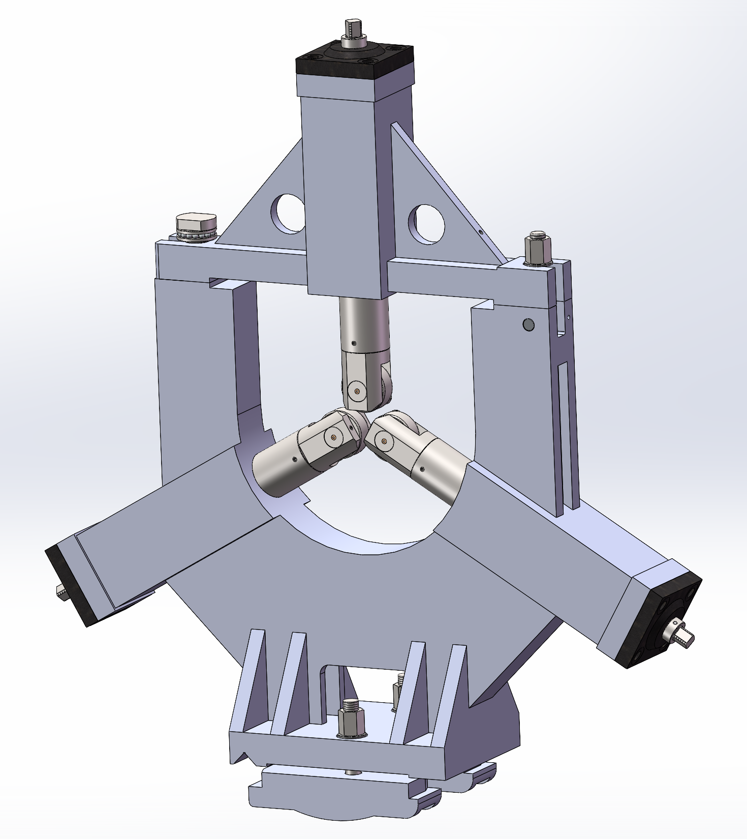
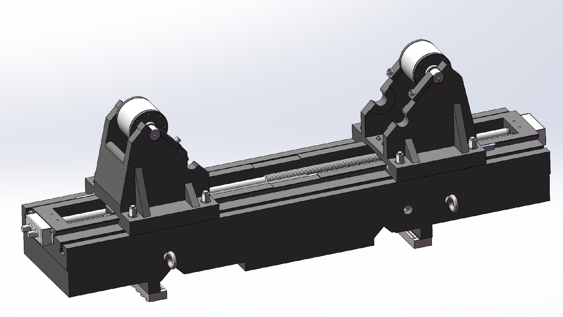
According to the characteristics of the workpiece, the machine tool can be equipped with a workpiece drag roller (two-point roller)
6.1 Optional SIEMENS 828D CNC system, including CNC control unit, drive amplifiers, and AC servo motors (2-axis synchronous control). Includes spindle encoder.
6.2 Tool geometry and wear compensation
6.3 Tool radius compensation
6.4 Direct dimensional drawing programming
6.5 Built-in programmable machine controller (PMC)
6.6 Linear and circular interpolation
6.7 Backlash and pitch error compensation
6.8 Manual electronic handwheel feed
6.9 External computer interface
6.10 Single/multi-start thread turning
6.11Self-manufactured electrical cabinet with logically arranged components. Equipped with air-cooled air conditioning for temperature control.
7. Attachment and Tool List
NO. | Name | Model and size | Unit | QTY |
1 | Four-Jaw Chuck | set | 1 | |
2 | Spindle Center Sleeve
| pc | 1 | |
3 | Tailstock Center Sleeve
| pc | 1 | |
4 | Tool Turret Wrench | pc | 1 | |
5 |
| pc | 1 | |
6 |
| pc | 1 | |
7 | Spindle Center
| pc | 1 | |
8 | Tailstock Center
| pc | 1 | |
9 | Double-Ended Wrench | 8×10 S91-1 | pc | 1 |
10 | Double-Ended Wrench | 12×13 S91-1 | pc | 1 |
11 | Double-Ended Wrench | 27×30 S91-1 | pc | 1 |
12 | Double-Ended Wrench | 32×36 S91-1 | pc | 1 |
13 | Double-Ended Wrench | 41×46 S91-1 | pc | 1 |
14 | Single-End Open-End Wrench | 16 S91-2A | pc | 1 |
15 | Single-End Open-End Wrench | 18 S91-2A | pc | 1 |
16 | Single-End Open-End Wrench | 21 S91-2A | pc | 1 |
17 | Single-End Open-End Wrench | 24 S91-2A | pc | 1 |
18 | Hex Key (Allen Wrench) | 6 S91-7 | pc | 1 |
19 | Hex Key (Allen Wrench) | 8 S91-7 | pc | 1 |
20 | Hex Key (Allen Wrench) | 10 S91-7 | pc | 1 |
21 | Hex Key (Allen Wrench) | 12 S91-7 | pc | 1 |
22 | Hex Key (Allen Wrench) | 14 S91-7 | pc | 1 |
23 | Hex Key (Allen Wrench) | 22 S91-7 | pc | 1 |
24 | Hook Spanner | 270-310 S93-1 | pc | 1 |
25 | Hook Spanner | 330 S93-1 | pc | 1 |
26 | Hook Spanner | 400 S93-1 | pc | 1 |
27 | Snap Ring Pliers | 3.0 S94-1A | pc | 1 |
28 | Single-End Open-End Wrench | 55 | pc | 1 |
29 | Chuck Mounting Wrench | pc | 1 | |
30 | Roller Steady Rest | Φ100-φ500mm | set | |
31 | Roller Steady Rest | Φ450-φ800mm | set | |
32 |
Traveling Steady | Φ400-φ850mm/ Φ600-φ1050mm/ Φ800-φ1250mm/ Φ1000-φ1450mm/ Φ1000-φ1450mm |
set |
8. Main component materials and heat treatment requirements
NO. | Item | Material | Processing/Treatment |
1 | Bed Guideways | HT300 | Stress relief annealing; Vibration aging after rough machining; Medium-frequency quenching of guideways |
2 | Headstock | HT200 | Stress relief annealing; Vibration aging after rough machining |
3 | Feed Box | HT150 | Stress relief annealing
|
4 | Main Gears | 45 or 40Cr | High-frequency quenching; Grinding |
9. List of Main Purchased Parts
NO. | Model | Item | Specification | QTY | Remark |
1 | Spindle Bearings | 1set | HRB/ZWZ/LYC | ||
2 | Screw Bearings
| set | NSK | ||
3 | 55kW | AC Servo Motor
| 1000 r/min | 1 | MK |
4 | X/Z-axis Servo Motors
| 27/36N.m | 1set | SIEMENS | |
5 | CNC system | SIEMENS 828D | 1set | SIEMENS | |
6 | Φ50×10 | X-axis Ball Screw
| 1set | Taiwan | |
7 | Φ80×20 | Z-axis Ball Screw
| 1set | Nanjing | |
8 | 4-station Electric Tool Turret | 400X400 | 1 | Changzhou Hongda/Wenling | |
9 | Main Electrical Components
| 1set | SCHENEIDER | ||
10 | X/Z-axis Reducers
| 1set | Newstart or equivalent | ||
11 | Manual Chuck | K78/Φ1000 | 1e | Wafangdian (WFT) |
10. Basic machine components
NO. | Item | QTY | Remark |
1 | Main Unit | 1pc | Includes control components & rapid traverse motor |
2 | Electrical Cabinet | 1pc | |
3 | Coolant Tank System | 1set | |
4 | Lighting Kit
| 1set | Mounted on main unit |
5 | Standard Accessories | See manual | Included in accessory case
|
11. Other Disassembled Parts
NO. | Item | Model | Specification | QTY | Remark |
1 | Anchor Bolts
| GB799-88 | M30×600 | 1set | |
2 | Hex Nuts (Rough)
| GB41-86 | M30 | 1set | |
3 | Flat Washers (Grade C) | GB95-85 | 30 | 1set | |
4 | Set Screws | GB83-88 | M24X80 |
12. Standard Technical Documentation
NO. | Document Name
| Remark |
1 | Operating Manual
| |
2 | Certificate of Conformance
| Includes precision inspection records |
3 | Packing List |
13. Acceptance of machine tools
13.1 Pre acceptance of machine tools
113.1.1 Pre acceptance is carried out by the manufacturer, and the acceptance item is precision inspection. The "Inspection Record Form" is filled out and serves as the basis for final acceptance.
13.1.2 The pre acceptance inspection tools shall be provided by the manufacturer.
13.2 Machine Tool Installation and Debugging, and Responsibilities of Both Parties
The manufacturer shall provide the installation condition diagram of the machine tool foundation to the user after the contract takes effect, and the user shall be responsible for the design and construction of the foundation, as well as completing the power connection of the equipment and the positioning work after receiving the equipment. The manufacturer shall send personnel to guide the installation of the equipment, responsible for precision calibration, debugging, and commissioning work. The user shall cooperate with the manufacturer to complete the debugging work.
13.3 Final acceptance of machine tools
After the installation and debugging of the equipment are completed, the final acceptance shall be carried out by the user;
13.3.2 Trial processing of national standard workpieces, meeting the requirements of the agreement, signing the final acceptance minutes, and both parties signing and approving.
13.3.3 The user shall be responsible for providing the final acceptance test specimens using the inspection tools.
14. Training
The manufacturer provides free training for the user's operation and maintenance personnel, and the specific training content is as follows:
The training will be conducted in two sessions, with the first session taking place during the pre acceptance period at the manufacturer's site. The second time will be conducted during the final acceptance period at the user's site. The number of participants in the training is 3-5 people.
15. Quality assurance and after-sales service
15.1 The quality assurance period of the machine tool is one year from the final acceptance. During this period, if there are any quality problems under normal use conditions, the manufacturer is responsible for free repair and replacement of damaged parts.
During the warranty period, if the machine tool malfunctions, the manufacturer shall respond within 48 hours after receiving notification from the user or send personnel to the user's site for effective handling.
15.3 After the warranty period of the machine tool expires, the manufacturer shall provide maintenance services to the user at the most favorable price.
Equipment optional list
NO. | Item | Optional Specifications | Remarks |
1 | Spindle Bearings | NSK/FAG/SKF | |
2 | Heavy-Duty 4-Jaw Chuck | K78 series (other sizes) | |
3 | Electric Tool Turret | Yantai Universal/Other brands | |
4 | Powered Tool Turret | BMT75/VDI50 | Brand: Taiwan/Germany/Italy |
5 | Simplified C-axis Indexing | Hydraulic brake (TW) | When selecting power turret, it must be equipped with |
6 | CNC System | KND2000T/FANUC | When selecting a power turret, it must be equipped with |
7 |
| Renishaw straight-arm type | |
8 | In-Process Measurement | Renishaw RLP40 wireless probe | |
9 | Dedicated Boring Holder | Reference bore: Φ300/260/200mm | |
10 | Internal Grinding HeadCustomized per workpiece diameter/length
| Customized per workpiece diameter/lengthCustomized per workpiece diameter/length
| |
11 | Cylindrical Grinding Head | 1.1kW, φ300 grinding wheel | |
12 | Tailstock Accessories
| Tapered discs, tailstock chucks, etc. |
Boring device (Optional according to the characteristics of the workpiece)
This machine is equipped with a boring unit capable of machining internal bores on workpieces. The boring unit is mounted on a dedicated, widened, and reinforced slide plate. The boring bar's rear section is supported by a linear guide installed on the carriage to maximize structural stiffness. A counterweight is added to the boring bar's rear based on machining requirements to ensure accuracy. The boring bar integrates an internal coolant pipe to cool cutting tools during operation.
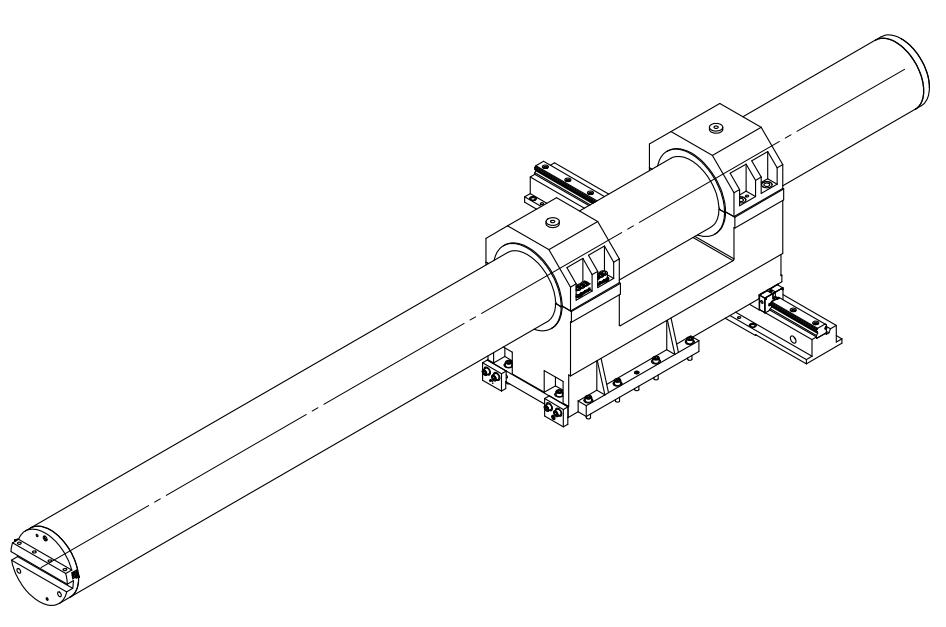
The benchmark hole of the boring tool holder can achieve φ300mm, with a set of seismic boring bars with a φ300mm, which can boring the maximum boring depth φ2400mm.
Product Parameters:

Whatsapp Code


 +86-151 6596 4868
 +86-151 6596 4868
 +86-151 6596 4868
 susan@novatechlathe.com
